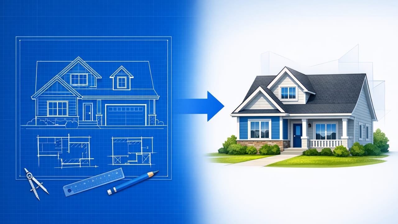
When you turn a blueprint into a 3D model, you’re not just creating a nicer picture—you’re translating a technical document into a spatial preview you can use to test layouts, validate renovation ideas, and communicate decisions clearly. The challenge is that most blueprints were never designed for automated 3D conversion: scans can be skewed, line weights vary, and critical information (like wall thickness or ceiling height) may be missing.
This guide walks through an accuracy-first workflow to convert a black-and-white blueprint into a clean 3D model. You’ll learn how to prep the source file, choose the right tool type, verify scale, handle doors/windows, and avoid the common errors that make 3D renders look “off.”
What “blueprint to 3D model” really means
In practice, blueprint-to-3D conversion usually means creating a dimensionally consistent 3D representation of:
- Walls and partitions (with correct thickness)
- Openings (doors, windows, arches)
- Levels (story heights, stairs, split levels)
- Key architectural features (columns, built-ins, niches)
- Basic materials and furniture (optional, for staging and planning)
Some workflows produce a full BIM model; others produce a visualization-ready mesh for 3D renders. For renovation previews and room planning, you typically need correct proportions and clean geometry more than construction documentation-level detail.
Step 1: Prepare the blueprint for conversion (quality in = quality out)
Before you model anything, make the blueprint easier to interpret. This step is the difference between a fast conversion and hours of cleanup.
Blueprint prep checklist
- Use the highest-quality source: PDF vector drawings are best; then high-resolution scans (300–600 DPI).
- Confirm the drawing scale: Look for a scale note (e.g., 1/4" = 1'-0") or a dimension you can trust.
- Remove visual noise: Crop margins, erase stamps, and reduce speckling if the scan is dirty.
- Fix skew/perspective: Scanned pages can be slightly rotated or stretched.
- Separate floors: If multiple levels are on one sheet, split them into separate images/pages.
Pro tip: If the blueprint is a scan, even a 1–2° rotation error can cause walls to miss-align after tracing—especially in long corridors.
Step 2: Choose the right conversion approach
There’s no single “best” way to turn a blueprint into a 3D model. The right choice depends on accuracy requirements, timeline, and your comfort level with 3D tools.
| Approach | Best for | Typical time | Pros | Cons |
|---|---|---|---|---|
| Manual CAD → 3D (trace + extrude) | Renovations needing high accuracy | Hours to days | Maximum control, precise dimensions | Steep learning curve |
| BIM workflow (Revit/Archicad) | Construction documentation, multi-level buildings | Days+ | Data-rich model, schedules, consistency | Overkill for simple previews; time-intensive |
| AI-assisted floor plan conversion | Fast renovation previews, room planning, staging | Minutes to hours | Quick 3D renders, easy iteration | Needs verification; may misread symbols |
| Outsource (drafting/3D artist) | Polished deliverables without DIY time | Days to weeks | Professional output | Cost; feedback cycles can be slow |
If your goal is to compare layout options, test furniture sizes, or explore finishes, AI-assisted conversion plus a strong accuracy checklist often delivers the best speed-to-confidence ratio.
Step 3: Establish scale and units (the make-or-break step)
Most blueprint-to-3D mistakes come from one source: incorrect scale. Even if the model “looks right,” wrong scale will break furniture fit, door sizing, and window placement.
How to set scale reliably
- Pick a known dimension on the plan (e.g., a 10'-0" wall segment or a labeled room width).
- Measure it in the source (pixels if it’s an image; units if it’s a vector PDF/CAD).
- Compute a conversion factor (pixels → feet/meters).
- Apply the factor consistently to all traced geometry.
If you’re working from a raster image and you want a quick way to compute scale, the logic is simple:
// Convert pixel distance to real-world distance
// known_real: real dimension (e.g., 3.048 meters for 10 feet)
// known_px: pixel length measured on the blueprint
// any_px: pixel length of another segment

scale = known_real / known_px
any_real = any_px * scale
Accuracy tip: Use the longest reliable dimension you can find (long wall, overall width). Longer reference distances reduce the impact of small measurement errors.
Step 4: Rebuild the 2D plan cleanly before going 3D
Whether you trace manually or use AI conversion, your 3D model is only as good as the underlying 2D interpretation.
What to standardize in 2D
- Wall types: interior vs. exterior, thickness differences, structural walls.
- Wall centerlines vs. faces: choose a consistent method (model to wall faces for interior fit accuracy).
- Room boundaries: ensure closed loops (helps with auto-floor creation and area checks).
- Openings: confirm widths and swing directions; remove duplicate lines near doors/windows.
Even in AI workflows, you’ll often benefit from a short “cleanup pass” where you confirm walls are straight, corners are closed, and unusual symbols (pocket doors, bay windows, fireplaces) are interpreted correctly.
Step 5: Convert to 3D (extrusion, levels, and openings)
Once the 2D plan is stable, the 3D stage becomes predictable.
Walls and heights
If ceiling heights aren’t specified, use a reasonable placeholder (for example, 8–9 ft / 2.4–2.7 m) and mark it as an assumption. In renovations, ceiling height affects:
- Cabinet and tile layouts
- Window proportions in renders
- Lighting placement and perceived room scale
Doors and windows
Blueprint symbols vary, so verify opening sizes rather than trusting the first pass. At minimum, confirm:
- Door width (common interior doors are often 28–36 inches / 710–910 mm)
- Window width and sill height (sill height is frequently missing on basic plans)
- Alignment (centered on wall segments vs. aligned to room features)
Floors, stairs, and multi-level plans
For two-story homes, model each level separately and align them using structural references (stair core, exterior walls). Stairs are a frequent source of errors; if your plan lacks rise/run details, treat the stair as conceptual until verified.
Step 6: Add context for renovation previews (materials + basic furnishings)
A purely architectural shell is accurate, but it may not answer the questions people actually have (“Will this sofa fit?” “Will the kitchen feel cramped?”). Adding light staging helps validate the design.
What to include (and what to skip)
- Include: key furniture footprints, kitchen counters, islands, major appliances, bathroom fixtures.
- Include: simple materials (flooring, wall color) to compare options.
- Skip (early on): tiny decor items, complex molding profiles, photoreal textures.
If you use an AI room planner, treat the results as a fast ideation layer. The best workflow is often: accurate shell → AI layout ideas → human selection → quick verification.
Accuracy checks: how to know your 3D model matches the blueprint
After you turn a blueprint into a 3D model, validate it with a short QA routine. These checks catch the most common mismatches without requiring advanced tools.
A 10-minute validation routine
- Overall footprint check: Compare exterior dimensions (width/length) to the plan.
- Room size check: Verify 2–3 key rooms (kitchen, primary bedroom, living room).
- Wall thickness check: Confirm exterior vs. interior thickness where specified.
- Door clearance check: Ensure doors don’t collide with fixtures or furniture.
- Window placement check: Confirm spacing to corners and alignment between floors.
- Circulation check: Walk the model—hall widths and pinch points become obvious in 3D.
Common pitfalls (and how to avoid them)
1) Assuming the scan is perfectly to scale
Scans can stretch unevenly. If something feels off, re-check scale using a different reference dimension on the opposite side of the plan.
2) Misreading symbols
Pocket doors, sliding doors, and cased openings can be confused. When in doubt, cross-reference notes, door schedules, or elevations.
3) Ignoring wall thickness changes
Older homes and renovations often mix wall types. If you use one thickness everywhere, room sizes drift and cabinetry fits poorly.
4) Treating 3D renders as construction documents
A 3D preview is ideal for decision-making and communication, but structural changes still require professional review and site measurement.
Exporting and sharing: make your model usable
Once your 3D model is validated, export formats and views should match your audience:
- For stakeholders: high-resolution 3D images from 2–4 angles per room.
- For contractors/designers: annotated screenshots with key dimensions and assumptions.
- For iteration: keep a versioned file naming system (e.g., Kitchen_OptionA_v3).
Documentation tip: Keep a short “assumptions list” (ceiling height, window sill height, wall thickness) attached to exports. It prevents misunderstandings later.
Putting it all together: a practical workflow summary
- Start with the cleanest blueprint you can get (prefer vector PDFs).
- Set scale using a long, trustworthy dimension.
- Rebuild/confirm 2D walls and openings before 3D.
- Extrude walls, set levels, and place doors/windows.
- Add minimal staging to test function and layout.
- Run quick validation checks and document assumptions.
- Export renders and share decision-ready views.
If you want a lightweight way to experiment with floor plan conversion and quick 3D renders on mobile—especially for renovation previews and redesign options—an iOS tool like Floor Plan to 3D & Home Redesign can help you move from blueprint to visual decisions faster, as long as you still verify scale and key dimensions.
