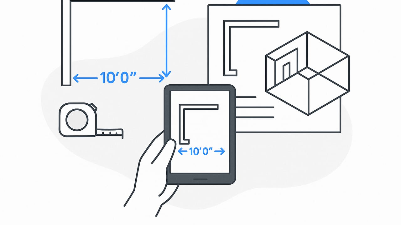
If you need to trace walls with measurements for an accurate floor plan, a reliable workflow will save you hours later. Whether you are documenting as-builts, planning a remodel, or preparing visuals for clients, the difference between a quick sketch and a solid measured trace is the difference between guesswork and decisions you can trust. This guide covers tools, step-by-step methods, error checks, and the handoff from field notes to clean 2D and 3D layouts.
What tracing with measurements really means
Tracing walls can be as simple as outlining a photo, but that rarely holds up in design or construction. When you trace walls with measurements, you anchor your lines to real-world dimensions, capture wall thickness and openings, and close loops with tolerances you can defend. The result: layouts that align with cabinetry, MEP rough-ins, and code-compliant clearances.
- Goal: A dimensionally faithful base plan that supports design, estimating, and visualization.
- Scope: Wall centerlines or faces, wall thickness, door and window openings, room widths/lengths, diagonals for squareness, ceiling heights, and critical offsets (e.g., fixture centers).
- Deliverable: A scaled trace or vector plan you can import into CAD/BIM or convert to 3D.
Tools that get you there (and when to use them)
| Tool | Typical precision | Best use | Notes |
|---|---|---|---|
| Laser distance meter (Class 2) | ±1/16 in (±1.5 mm) | Most interiors | Quick, reliable; watch reflective glass and angled hits. |
| Tape measure (25–100 ft) | ±1/8 in (±3 mm) | Short runs, openings | Good for verification; needs two hands for long pulls. |
| Phone LiDAR / room scanner | ±1–2% of span | Speed mapping | Great for context; confirm key dimensions with laser. |
| Laser level / plumb line | n/a | Vertical alignment | Use for tall ceilings, stair runs, and alignment checks. |
| Angle finder / digital protractor | ±0.3° | Non-90° corners | Shortens iteration when rooms are out of square. |
Pro tip: combine a laser distance meter for spans and a tape for openings and finishes. Use a quick phone scan to capture context, then refine with measured strings.
Before you start: set up for accuracy
- Pick a datum: Choose a consistent origin (e.g., the front-left exterior corner or a lobby column center). All dimensions reference this.
- Decide units and rounding: Work in feet-inches or millimeters. Agree on rounding (e.g., to the nearest 1/8 in or 5 mm) and stick to it.
- Face vs. centerline: For interior partitions, measure to finished face. For structural layout, consider centerline. Note which you used.
- Wall thickness: Measure a few representative walls; note variations (e.g., 4-7/8 in gypsum over metal stud vs. 5-1/2 in 2x4 with drywall).
- Plan your loops: Choose rooms or zones where you can start at a corner and return to it. Closed loops reveal cumulative error.
Step-by-step: trace walls with measurements
1) Sketch first, measure second
Make a quick, rough diagram of the space: walls, doors, windows, and any jogs. Mark a North arrow and your datum. Label rooms and give each a unique code (e.g., A101, A102).
2) Wall-by-wall running dimensions
Pick a start corner. Walk clockwise. For each wall:
- Record the wall length (face-to-face) to the nearest 1/8 in.
- Capture openings: Measure from the start corner to the near jamb, opening width, and height. Note sill height for windows.
- Note wall thickness transitions at columns or shaft walls.
Example notation on your sketch: W1 = 15'-3 1/2', Door D1 @ 4'-2 3/8' from corner, 2'-10' leaf, RH swing.
3) Diagonals and squareness
Rectangular rooms should have equal diagonals. After measuring two adjoining sides, shoot the diagonal. If diagonals differ by more than 1/2 in for a 12–16 ft room, note the out-of-square condition. For L-shaped rooms, measure diagonals of constituent rectangles or add a third diagonal across the long span.
4) Heights and levels
- Ceiling height (CH): Measure at two opposing corners. If there is a slope or soffit, note start and end heights and the offset from walls.
- Floor level changes: Step heights at thresholds and stairs, measured riser and tread.
5) Irregular geometry
- Bay windows / chamfers: Measure each segment length and the included angle, or measure the two side lengths and the chord across the bay plus the orthogonal offset to the apex.
- Curved walls: Use chord-and-arc. Measure chord length and mid-chord offset. Radius R ≈ (C²/(8h)) + (h/2), where C is chord and h is sagitta. Mark arc direction.
- Oblique corners: Record angle with an angle finder, or measure a triangle: two sides from a vertex and the included angle.
6) Services and fixtures
Centerlines matter. Note sink, toilet, range, and radiator centerlines from the nearest two walls (X and Y), rough openings for built-ins, and electrical panel locations with clearances.
7) Close the loop
Return to the start corner and measure the closing distance. Your summed wall lengths minus the closing distance should reasonably match the perimeter. Record the closure error for QA.
Field mantra: Measure twice where it hurts once later—corners, diagonals, and door-wall offsets.
Quality assurance: tolerances and error control
Your plan doesn’t need to be perfect—just within a clear tolerance. For residential interiors, aim for:
- Linear wall lengths: ±1/4 in for spans under 20 ft; ±3/8 in above 20 ft.
- Door/window widths: ±1/8 in (finish critical).
- Room diagonals: within ±1/2 in of each other for spans under 20 ft.
- Loop closure: ≤ 0.2% of loop perimeter (e.g., 0.48 in on a 200 ft loop).
If your loop closure is off, distribute the error proportionally across wall segments rather than dumping it into one wall. Flag any walls that already control critical fits (e.g., kitchens) and adjust the less critical ones.
Simple closure check (example)
# Pseudocode to check loop closure and distribute error
segments = [15.29, 10.50, 15.33, 10.46]  # feet (converted from measured inches)
perimeter = sum(segments)
dx = -0.08  # feet (negative if measured loop is too long by 0.96 in)
adj = [s/perimeter * dx for s in segments]
corrected = [s + a for s, a in zip(segments, adj)]
Keep both the original and corrected values. The original is your field truth; the corrected supports clean drafting.
Turning a photo or scan into a scaled trace
Many workflows start with a photo or scanned plan. To trace walls with measurements in software, you need scale. Two common approaches:
Approach A: Known dimension scale-up
- Import the image into your drawing app.
- Draw a line over a known dimension (e.g., hallway measured at 12'-0').
- Use the scale tool so your line equals the known length; lock aspect ratio.
- Trace wall centerlines or faces, snapping your lines to the scaled image.
Approach B: DPI and scale factor
If you scanned at a known DPI and have a printed scale (e.g., 1/4 in = 1'-0'), compute pixels per foot:
# Pixels per foot at 300 DPI for 1/4 in = 1'-0' drawings
dpi = 300
inches_per_foot_on_paper = 0.25
pixels_per_foot = dpi * inches_per_foot_on_paper  # 75 px/ft
Draw guides at multiples of 75 px to spot gross mis-scales and to check alignment while you trace.
Door and window measurements that save rework
- Record swings and handing: RH/LH, in-swing/out-swing. Sketch the arc.
- Jamb-to-jamb, not trim-to-trim: Measure rough opening if visible; otherwise, note finish type.
- Heights: Standard doors are often 6'-8', but measure—older buildings vary.
- Window sill/head: Sill height from finished floor and head height to ceiling or soffit.
These details drive furniture clearances, egress checks, and daylight modeling.
Special cases: slopes, thick walls, and structure
- Stair runs: Count risers, measure one typical riser/tread, and total run. Confirm headroom along the nose line.
- Thick walls: For masonry or multi-layer assemblies, capture both faces and the core thickness where possible. Mark if wall is load-bearing.
- Columns and offsets: Dimension to column centerlines from two perpendicular walls; note sizes and wraps.
From trace to 2D and 3D: clean modeling
- Draft the shell: Draw walls using the measured lines; lock your units and precision to your field rounding.
- Apply wall types: Assign thicknesses and materials; align to the measurement reference you used (face or centerline).
- Place openings: Insert doors and windows with exact offsets and sizes. Assign swing and sill/head heights.
- Run a dimension QA: Pull dimension strings across each room; compare to field notes. Adjust only within your tolerance budget.
- Generate 3D: Extrude walls to measured ceiling heights, add floors/ceilings. Spot-check in perspective for visual clashes.
When you preserve measured relationships in 2D, 3D becomes a trustworthy visualization instead of a guess.
Common pitfalls (and quick fixes)
- Measuring to trim: Trim lies. Measure to hard surfaces (jambs, finished faces). Note baseboard thickness only if it affects critical clearances.
- Laser misses: Shiny glass or angled hits can return long reads. Tilt slightly, use a target card, or switch to a tape for that span.
- Forgetting diagonals: Rectangles that aren’t square won’t close cleanly in CAD. Always shoot at least one diagonal per room.
- Unmarked level changes: A single step can invalidate appliances or accessibility clearances. Circle them in your sketch.
- Mixing units: Consolidate everything into one unit system before drafting. Note conversions explicitly.
Field checklist: trace walls with measurements
- Sketch per room with datum and North arrow
- Wall-by-wall lengths and wall thickness notes
- All doors/windows with offsets, sizes, swings, and heights
- At least one diagonal per room (more for irregular shapes)
- Ceiling heights and soffit dimensions
- Fixture centerlines and critical clearances
- Loop closure captured and tolerance applied
Example measurement template
Room,Ref Wall,Run Start,Run End,Length (in),Openings,Height (in),Notes
A101,W1,Corner A,Corner B,183.5,"D1 @ 50.4, 34.0 wide, RH",108,Plaster wall 5.0 in
A101,W2,Corner B,Corner C,125.0,"W1 @ 40.0, 36.0 wide, sill 30",108,Soffit @ 16 in deep
A101,Diagonal,Corner A,Corner C,224.7,,,
Store your notes as CSV or in a notes app so you can import them to a spreadsheet and run automatic checks (e.g., closure percentage, min door clearances).
Accuracy vs. speed: finding the balance
Not every project needs millimeter precision. Match your approach to the decision you need to support:
- Concept planning: Quick phone scan + key laser checks on room widths and door sizes. Tolerance ~1%.
- Fixture layout: Full wall-by-wall trace with openings and centerlines. Tolerance ~0.2%.
- Fabrication/permits: Comprehensive as-builts with verified diagonals, heights, and structural elements. Tolerance ~0.1–0.2%.
Document your tolerance so stakeholders know how far they can push dimensions before a re-measure is required.
FAQ: quick answers
Do I measure to finished face or framing?
For interior layouts and furniture/appliance fit, measure to finished faces. For structural coordination or framing plans, use centerlines or framing edges and note the finish build-ups separately.
How do I handle curved walls without a template?
Measure at least two chords and sagitta offsets along the curve. Use the average calculated radius or spline through measured points. Mark the direction of curvature and verify with a third spot measurement.
How much closure error is acceptable?
As a rule of thumb, keep closure under 0.2% of the loop perimeter. If it exceeds that, re-check key spans and diagonals before distributing the error.
Wrap-up: from site notes to reliable plans
To trace walls with measurements is to turn a space into data: a consistent datum, measured spans, verified diagonals, and documented openings. With a clear QA routine and a realistic tolerance budget, you can translate field truth into clean 2D and 3D models that support confident decisions. If you prefer to start from existing black-and-white floor plans and visualize them spatially, the iOS app Floor Plan to 3D can convert your 2D layout into an accurate 3D render while preserving dimensions for proposals and planning.
