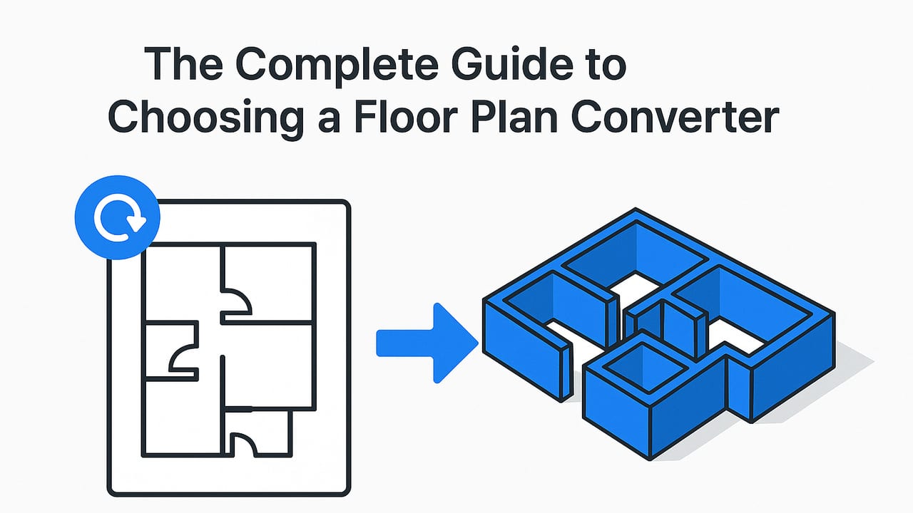
A floor plan converter bridges the gap between 2D drawings and spatially accurate 3D models. Whether you are planning a renovation, staging a listing, or preparing a design presentation, converting a floor plan quickly and accurately can save hours of work and reduce costly on-site surprises. This guide explains how floor plan converters work, what accuracy really means in practice, how to choose the right approach for your needs, and how to structure a reliable workflow from import to validation.
What a Floor Plan Converter Actually Does
At its core, a floor plan converter ingests a floor plan (scan, photo, PDF, or vector file) and outputs a structured model or drawing you can measure, edit, and visualize. Depending on the tool, you may receive one or more of the following:
- Vector 2D geometry (DWG, DXF, or SVG) with walls, doors, windows, and annotations on layers.
- 3D models (OBJ, GLB/GLTF, FBX) suitable for visualization and furniture layout.
- BIM-like data (IFC) with walls, slabs, openings, and metadata for downstream coordination.
The best floor plan converter preserves proportions, interprets wall thickness, identifies openings, and respects scale. Some solutions also infer finishes, ceiling heights, and room names from text annotations and symbols.
Before You Convert: Input Quality and Preparation
Your output can only be as good as your input. Optimizing the source plan reduces errors and cleanup time:
- Capture cleanly: If photographing, stand directly above the plan, avoid skew, and use even lighting. Fill the frame with the drawing while keeping borders visible.
- Scan smart: Scan at 300–600 dpi for line art. Use black-and-white or grayscale to keep line edges crisp and file size reasonable.
- Straighten and crop: De-skew and crop out unrelated notes or title blocks that might confuse automatic detection.
- Preserve scale: Keep at least one dimension string or a scale bar visible. If none exists, include a known-length object in the photo for later calibration.
- Clarify symbols: If possible, include a legend for doors, windows, and stairs to reduce misinterpretation.
Accuracy Fundamentals for a Floor Plan Converter
Accuracy isn’t a single number; it’s a set of tolerances you define for your project. Consider these components:
- Scale calibration: The relationship between pixels and real-world units must be established from a known dimension. Avoid rounding early; small errors compound.
- Wall logic: Tools infer wall centerlines or edges. Ensure thickness is consistent with the source plan, especially at intersections.
- Openings: Door swings, window widths, and sill/head heights matter for furniture clearance and daylight studies. Provide defaults when the plan is silent.
- Vertical data: Ceiling and slab heights may need manual input. If only 2D data exists, set clear defaults (e.g., 2.6 m ceilings) and document them.
- Multi-level continuity: Verify stair alignments and floor-to-floor transitions so 3D navigation and calculations make sense.
Define acceptable error bands up front. For space planning, a wall-to-wall length deviation within ±2% (or ±20 mm on a 1 m run) may be acceptable. For fabrication or millwork, tighten that tolerance significantly.
Types of Floor Plan Converters: Pros, Cons, and Use Cases
Different projects call for different conversion methods. Here is a quick comparison:
| Method | Strengths | Limitations | Best For |
|---|---|---|---|
| Manual CAD Tracing | Highest control; layer discipline; standard outputs | Time-consuming; skill-dependent | As-builts, permit sets, detailed coordination |
| Semi-Automatic Vectorization | Accelerated tracing; preserves structure | Needs cleanup; struggles with noisy scans | Concept validation, iterative sketches |
| AI Mobile/Cloud Converters | Fast; camera-to-3D; intuitive | Assumptions for heights/materials; QA needed | Real estate, early design, quick visualizations |
| LiDAR/Photogrammetry | Captures actual conditions; 3D context | Requires site access; heavier files | Renovations, historic documentation |
| Outsourced Drafting | Offloads labor; flexible staffing | Variable QA; turnaround time | Large backlogs, batch conversions |
Floor Plan Converter Workflow: A Step-by-Step Path
- Collect inputs: Gather all plan sheets, revisions, and any dimensioned elevations. Choose the cleanest source.
- Preprocess: De-skew, crop, and increase line contrast. Remove unrelated notes that could confuse detection.
- Calibrate scale: Use a known dimension; avoid rounding. Save the calibration factor with the file.
- Detect structure: Convert walls, doors, windows, and stairs. Confirm wall thickness and alignment at junctions.
- Annotate rooms: Label room names and apply default ceiling heights where missing.
- Extrude to 3D: Generate 3D walls, slabs, and openings. Add levels for multi-story models.
- Furnish and light: Add furniture, materials, and lighting only after geometry is verified.
- Validate: Run dimensional checks and area comparisons. Export a QA report.
If you are calibrating scale from an image, a simple pixel-to-meters conversion helps sanity-check results:
# Example: compute real-world length from pixel distance
# Input: pixels (px), scan resolution (dpi), units = meters
# 1 inch = 25.4 mm; 1000 mm = 1 m

def pixels_to_meters(pixels, dpi):
    mm = (pixels / dpi) * 25.4
    return mm / 1000.0

# Example: 950 px at 300 dpi ≈ 80.5 cm
print(pixels_to_meters(950, 300))  # 0.8047 m
Quality Checks That Keep You Honest
Trust but verify. A robust floor plan converter workflow includes measurable QA gates:
- Linear check: Compare 8–12 random dimensions (short, medium, long runs). Record absolute and percent error.
- Area check: Compute room areas before and after conversion; deviation should typically be within ±2–3% for planning.
- Topology check: Doors should not intersect walls improperly; stairs must connect levels; rooms should be closed polygons.
- Adjacency sanity: Kitchens next to living areas? Bathrooms stacked vertically? Catch adjacency anomalies early.
- Opening inventory: Count doors and windows per room and compare to the plan.
Convert once, check twice. QA is cheaper than rework.
The Right Outputs: Formats and Interoperability
Match the converter’s exports to your downstream tools:
- DWG/DXF: Ubiquitous 2D/3D CAD. Ensure proper units (mm or m) and layer naming for walls, doors, windows, text.
- SVG/PDF: Lightweight vector for quick editing and documentation, not ideal for BIM coordination.
- OBJ/GLTF/FBX: Great for visualization and web viewers; preserve real-world scale and origin.
- IFC: If you need BIM semantics, IFC helps transfer walls, slabs, and openings with categories.
Set a consistent coordinate system and naming conventions (e.g., L-WALL, L-DOOR, L-WINDOW). Include a scale note and a change log with assumptions (default ceiling height, missing dimensions inferred, etc.).
Visual Realism vs. Technical Fidelity
It’s tempting to jump straight into photorealistic materials and lighting, but invest first in geometric fidelity. A reliable floor plan converter workflow prioritizes:
- Correct wall positions and thickness over sophisticated textures.
- Accurate openings over decorative door models.
- Clear layer structure over heavy entourage that bloats files.
Once geometry is locked, add materials, daylight, and furniture to convey intent. Keep render settings consistent across comparisons to avoid misleading impressions.
Common Pitfalls and How to Avoid Them
- Scale drift: Calibrate from multiple dimensions across the sheet to avoid localized distortion.
- Ambiguous stairs: Confirm up/down direction and riser counts; misreads can ruin multi-level alignment.
- Window height assumptions: If head and sill are unknown, document defaults and revisit when data improves.
- Thick annotation noise: Clouds, stamps, or hatches can be mistaken for walls—clean them in preprocessing.
- Non-orthogonal geometry: Many homes have angled walls; ensure your converter respects arbitrary angles, not only 90°.
Where a Floor Plan Converter Saves the Most Time
When applied thoughtfully, conversion tools remove repetitive tracing and enable faster iteration:
- Real estate and marketing: Generate consistent 3D views for listings and brochures.
- Renovation planning: Test furniture layouts and kitchen/bath redesigns without full site modeling.
- Client presentations: Improve stakeholder understanding with walkable 3D and clear room labels.
- Early design studies: Rapidly explore adjacencies, sightlines, and daylight access.
Checklist: Selecting and Using a Floor Plan Converter
- Confirm supported inputs (JPG, PNG, PDF, DWG) and outputs (DWG, GLTF, IFC).
- Test scale calibration on a known dimension and verify with at least five spot checks.
- Ensure the tool recognizes doors, windows, and stairs—or supports quick manual fixes.
- Look for layer control and unit settings; avoid locked or proprietary structures.
- Check multi-level support and how levels are defined and exported.
- Run a small pilot: convert one page, validate, then scale up.
- Document assumptions (heights, materials) and keep a change log.
- Automate QA where possible and archive the raw input alongside outputs.
Putting It All Together
A great floor plan converter won’t replace professional judgment, but it will accelerate it. Focus on input quality, scale discipline, and repeatable QA. Choose outputs that fit your next steps—CAD detailing, BIM coordination, or 3D visualization—and keep a tight loop between geometry and reality. When in doubt, measure twice and model once.
If you prefer an on-the-go approach on iPhone or iPad, the iOS app Floor Plan to 3D can transform black-and-white 2D plans into accurate 3D visuals and export high-resolution images for presentations.
