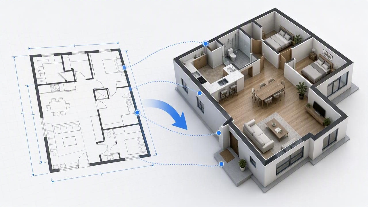
When a 2D floor plan becomes a 3D model, the most important promise is accuracy. If the conversion warps scale even slightly, furniture will not fit, door swings will clip, and circulation clearances will be unreliable. This guide gives a practical, step by step workflow to preserve measurements when building 3D spaces from floor plans, with quality control steps, tolerance targets, and export tips you can use on any project.
How to preserve measurements converting floor plan to 3d
Accuracy is won or lost before you place the first wall in 3D. The essentials below keep dimension fidelity intact from capture to final render.
1. Start with the cleanest possible source
- Scan instead of photographing if possible. Flatbed or mobile scanning yields less lens distortion than a handheld camera.
- If you must use a camera, capture head on, center frame, and fill the frame. Avoid angled shots that introduce perspective skew. Use gridlines to align edges, and enable automatic perspective correction sparingly; overcorrection can warp scale.
- Crop margins without cutting off scale bars, room labels, or key dimensions. Trimming away borders reduces auto detection errors while keeping alignment references.
- Normalize contrast. Increase contrast or use a threshold filter so walls are solid and gaps are clean. Remove stains and shadows that can confuse automation.
- Prefer vector plans when available. PDFs exported from CAD retain vector data that many tools can interpret with less error than raster scans.
2. Establish units and a robust scale anchor
You need at least one trustworthy reference dimension to set the global scale. More anchors are even better for verification.
- Use printed scale bars first. If the plan includes a bar scale, measure that in the image and compute the pixel to unit ratio.
- Fallback to explicit dimensions. Pick the longest labeled dimension on the plan, such as the overall building width. Longer spans reduce percentage error.
- Avoid inferring from symbols like typical door width, since doors vary by region and era. Known, labeled dimensions are safer.
- Confirm units. Are dimensions metric or imperial NTS not to scale drawings cannot be scaled reliably.
3. Compute a precise scale factor
Whether your tool sets scale automatically or you do it manually, the math is simple: scale factor equals true length divided by measured length in the image or import.
# Python example using single quotes to avoid double quote characters
# Given: a reference line measures 963.0 pixels in the image
# and the labeled true length is 6400 mm

pixels = 963.0
true_mm = 6400.0
scale_factor_mm_per_pixel = true_mm / pixels  # 6.646

# Apply to any measured pixel length:
def px_to_mm(px):
    return px * scale_factor_mm_per_pixel

# If your 3D scene uses meters:
def px_to_m(px):
    return px_to_mm(px) / 1000.0
Most 3D tools let you enter a numeric scale factor or snap two points to set scale. Use the longest straight segment you can reliably trace between labeled endpoints.
4. Snap to the right geometry
- Decide whether you model to wall centerlines or finish faces. The plan should make this explicit. Mixing conventions introduces drift.
- Respect wall thickness. Exterior walls often differ from interior partitions. Capture thickness accurately, not just the centerline alignment.
- Model structural openings with their rough opening size if noted. If only clear widths are labeled, use those consistently.
5. Use an alignment grid and lock it
Once your first two perpendicular walls are placed, set an orthogonal grid and lock them. Snap subsequent geometry to that grid to prevent micro rotations that add error across rooms.
6. Verify with cross checks as you go
- After key walls are placed, measure diagonals of rectangular rooms. If both diagonals match within tolerance, the rectangle is truly orthogonal and scaled.
- Spot check door to corner offsets and window heights. Variations here often point to earlier alignment drift.
From plan scale to 3D scale, step by step
Suppose your plan is drawn at 1 unit equals 50 units in metric, or a common imperial scale such as one quarter inch equals one foot. Here is a general conversion approach without relying on printed inch marks.
- Identify one labeled overall dimension. Example: overall living to kitchen length equals 7.8 meters.
- Measure that same segment in your imported plan image. Example: 1173 pixels.
- Compute the ratio. 7.8 meters divided by 1173 pixels equals 0.006648 meters per pixel.
- Set the plan image scale in your 3D tool using the computed ratio, or use the built in measure tool to scale by snapping the two endpoints to equal 7.8 meters.
- Lock the image or traced 2D underlay to prevent accidental rescaling.
Pro tip: establish two independent anchors on perpendicular axes. If X and Y scale independently match within tolerance, your image is not skewed. If they do not, correct perspective before continuing.
Wall thickness, openings, and elevation data
Many measurement problems come from ignoring the Z dimension. A 3D scene with correct plan dimensions can still mislead if heights are generic or if openings do not cut correctly.
- Set story heights early. If the plan notes finished floor to ceiling heights per room, enter them. If not, pick a reasonable default and flag rooms with atypical heights such as soffits and double height spaces.
- Capture sill and head heights for windows. If only bottom or top is known, compute the other using the window height.
- Mind stair runs and risers. If the plan lists total rise and tread counts, ensure the product equals floor to floor height and code compliant riser counts.
- Include structural thickness when it affects clearances. Slabs, beams, and dropped ceilings can reduce clear heights.
QA workflow and tolerances
Set tolerance targets that match the use case. Not every project needs millimeter precision, but you should know your acceptable error band.
| Use case | Suggested tolerance | Notes |
|---|---|---|
| Real estate marketing and staging | Plus or minus 2 percent or 25 mm, whichever is larger | Enough for furniture fits and circulation visuals |
| Interior design concepting | Plus or minus 1 percent or 15 mm | Cabinet modules and appliance clearances start to matter |
| Pre construction visualization | Plus or minus 0.5 percent or 10 mm | Use field verified dims for critical areas |
| Permit and fabrication | Not recommended from 2D image only | Use CAD or field survey as authoritative source |
Checkpoint list you can reuse
- At least one long dimension used to set scale
- Second dimension on the perpendicular axis within tolerance
- Two or more room diagonals checked
- Random spot checks on door offsets and window centers
- Story height confirmed and stairs validated against floor to floor
- Export measurement overlay for client or team review
Common causes of scale drift
- Perspective skew. Photographed plans at an angle stretch one axis. Fix with perspective correction before scaling.
- Barrel or pincushion distortion. Wide lenses curve lines. Step back and zoom in to reduce distortion, or crop to the central area.
- Mixed conventions. Modeling some walls to centerlines and others to faces introduces compounding errors at corners.
- Rounding when entering dimensions. Avoid rounding mid workflow; enter exact values and let the tool round for display only.
- Rescaling the underlay mid project. Lock the plan raster or vector underlay once scale is set.
- Unit mismatches. Confirm metric or imperial throughout, including in export dialogs.
Furniture, fixtures, and the impact of scale
Preserving measurements is not only about walls. Incorrect furniture scale can make a perfect plan feel wrong.
- Use manufacturer dimensions for key pieces like sofas, beds, and appliances. Swap placeholder blocks for measured models before final renders.
- Maintain consistent clearance standards. For example, dining chair pull back, kitchen work aisles, and door swings. If a clearance fails after scaling furniture properly, the issue is likely in the shell model.
- Align fixtures to rough in centers and distances. A toilet offset from the wall by 305 mm is typical in many regions; ensure the model matches local norms if the plan is not explicit.
Advanced: multi anchor scaling for skewed plans
If your source plan is slightly skewed and cannot be perfectly corrected, apply a two axis scale where X and Y are scaled independently. Some tools support non uniform scaling of an image before tracing. Workflow:
- Measure one long horizontal dimension and compute scale for X.
- Measure one long vertical dimension and compute scale for Y.
- Apply non uniform scaling to the plan underlay so both axes match their anchors.
- Trace after scaling, then lock the underlay.
After tracing, the modeled geometry should be uniform. Avoid non uniform scaling of the final 3D model itself, which can distort objects.
Documenting accuracy for stakeholders
Stakeholders want to know where numbers come from. Include a short accuracy note in your deliverables.
- State the scale method. Example: model scaled using overall building width from plan dimension.
- List tolerance targets and achieved checks. Example: four spot checks within plus or minus 12 mm over 8.0 m spans.
- Declare unknowns. Example: ceiling heights assumed at 2.6 m except where noted.
- Attach a measurement overlay image or PDF with key dims called out.
Exporting renders and preserving true scale in outputs
Renders are images without inherent scale. If clients need scale context:
- Add a graphic scale bar on floor plan or axonometric views.
- Include a dimensioned floor plan view alongside perspective renders.
- Choose export resolutions that keep line weights legible. For A3 prints, 300 dpi often suffices; for large posters, go higher.
- Do not resample images after export. Resampling can blur line edges and complicate scale interpretation.
Checklist: before you call it done
- Source cleaned and aligned
- Global scale set from a long labeled dimension
- Per axis check passed within tolerance
- Room diagonals validated
- Heights and openings set
- Furniture and fixtures at manufacturer sizes
- Export package includes accuracy note and optional scale bar
Summary
To preserve measurements when converting a floor plan into 3D, lock down the fundamentals: high quality capture, trustworthy scale anchors, disciplined snapping and alignment, and continuous verification. Tolerances should match the project’s purpose, and documentation should make assumptions transparent. With a predictable workflow, you will spend less time fighting scale drift and more time exploring design options with confidence.
On iOS, the Floor Plan to 3D app can ingest a black and white plan, detect walls and openings, keep dimensions tied to your reference anchors, and export high resolution 3D images for presentations, which pairs well with the accuracy practices above.
