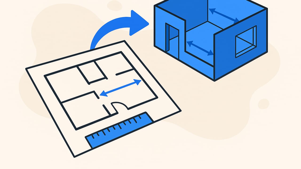
Whether you are planning a remodel, staging a listing, or preparing a design proposal, scale integrity is non-negotiable. If a wall is off by even a few inches, cabinetry won’t fit, clearances fail, and budgets slip. This guide explains practical, repeatable methods to ensure accurate room dimensions are preserved in 3D model outputs when working from 2D floor plans, scans, or photos.
What 'accuracy' means in a room-scale 3D model
Accuracy isn’t a single number. It’s a set of measurable criteria that define how faithfully the 3D geometry represents the plan. Consider these metrics:
- Absolute dimensional error: Difference between a known real-world dimension and the model dimension (for example, 10 ft measured vs. 9 ft 11.5 in in model).
- Relative error (%): The absolute error divided by the real dimension, useful for mixed-size spaces.
- Angular fidelity: Walls intended to be perpendicular should be 90°, not 89.2°.
- Proportional consistency: Door openings, stair treads, and fixture offsets scale correctly relative to the room.
- Accumulated drift: Long runs or multi-room sequences do not gradually deviate from reality.
Rule of thumb: For residential space planning, keep linear error within ±0.5–1.0 in on rooms up to 20 ft, and under 0.5–1.5% for larger spans. For cabinetry, aim tighter: ±0.25–0.5 in.
Establishing scale: from paper or photo to real measurements
The most important step is deriving a trustworthy scale factor before drawing or extruding anything. If you get scale right early, everything else stays consistent. If you don’t, downstream edits will compound errors.
1) Capture clean source imagery
- Use a flat, undistorted image: If photographing a paper plan, shoot straight-on, centered, with the camera parallel to the page. Avoid wide lenses that introduce barrel distortion.
- Scan when possible: A 300–600 DPI scan reduces perspective skew and ensures sharp line edges.
- Include a reference: Feature the printed scale bar, a dimension callout, or a known object length (for example, a 3 ft door).
2) Derive a scale factor
Once you have a clean image, compute the ratio between pixels and real-world units using a known distance on the plan.
- Pick two points with a printed dimension (for example, a 10 ft wall). Measure their pixel distance in your software.
- Compute the pixel-to-unit ratio.
- Apply this ratio consistently to every entity you trace or extrude.
# Example: compute scale factor and convert pixel distance to inches

# Known real-world length
known_length_in = 120.0   # 10 ft = 120 inches

# Measured in the image editor
pixel_length = 842.0

# Scale factor: inches per pixel
in_per_px = known_length_in / pixel_length

# Convert any pixel measurement to inches
another_wall_px = 1035.0
another_wall_in = another_wall_px * in_per_px

print('Wall length (in):', round(another_wall_in, 2))
3) Handle printed plan scales correctly
- Common scales: 1:50 (metric), 1:100, 1/4 in = 1 ft (imperial), 1/8 in = 1 ft.
- Convert carefully: At 1/4 in = 1 ft, 1 in on paper equals 4 ft in reality.
- Double-check with a second known length: Validate the scale using a different dimension on the sheet to catch scan DPI mistakes or image resizes.
Proving it: validation workflows to keep dimensions trustworthy
Verification should be systematic, not casual eyeballing. The goal is to have accurate room dimensions preserved in 3D model deliverables you can sign off with confidence.
Baseline checks
- Triangulate: Validate at least three independent distances per room: width, length, and a diagonal. Diagonals reveal skew that orthogonal checks can miss.
- Corner sanity: Confirm 90° corners using angle tools. If the plan is intentionally off-orthogonal, record exact angles to avoid assumptions.
- Door and window checks: Verify openings and sill heights; small errors here affect furniture and ADA clearances.
Overlay method
- Trace the plan in 2D with your scale factor applied.
- Extrude to walls and place openings.
- Export a top view of the 3D and overlay it on the source image at the same scale. Opacity-blend to spot deviations.
Dimension audit
- Wall-by-wall sweep: Use your software’s dimension tool to tag every primary wall and compare against the plan’s callouts.
- Cumulative spans: Sum room widths along a corridor and compare the total to the aggregated plan dimension.
- Tolerances: Establish a pass/fail threshold (for example, ±0.5 in) and flag exceptions.
Common pitfalls that distort scale
- Perspective skew: Photos shot at an angle cause non-uniform scaling; fix with perspective correction before measurement.
- Unknown DPI: Resized images break the relationship between pixels and real units; always re-derive the scale factor after any image edit.
- Barrel/pincushion distortion: Wide lenses bend lines; use lens profiles or crop to central regions for measurement.
- Rounding of plan callouts: Plans may round to the nearest inch; verify with a second length to avoid systematic bias.
- Ignoring wall thickness: Measuring to centerlines vs. finish faces changes room clearances; be explicit about which reference you use.
- Snap-to-grid errors: Over-aggressive snapping nudges endpoints off-scale; temporarily disable snapping during precise placement.
Tooling options: manual tracing, CAD imports, and AI converters
Different workflows trade speed for control. Choose one that preserves fidelity without wasting time.
| Workflow | Typical accuracy | Time investment | Skill level | Best for |
|---|---|---|---|---|
| Manual tracing in modeling software | High if scale is set correctly; human QC needed | Moderate to high | Intermediate | Bespoke spaces, unusual geometries |
| CAD import (DWG/DXF) to 3D | Very high; linework already scaled | Low to moderate | Intermediate to advanced | Professional drawings, multi-room projects |
| AI image-to-3D from floor plan | High if the engine respects scale references | Low | Beginner to intermediate | Quick visualization from scans/photos |
| LiDAR/photogrammetry | High for as-built capture; may need cleanup | Moderate | Intermediate | Existing spaces without reliable plans |
Case example: correcting an off-angle bedroom photo
Scenario: You have a paper plan for an 8 ft by 10 ft bedroom and only a smartphone photo taken at a slight angle. The goal is to create a 3D model with credible dimensions.
- Perspective correction: In an image editor, align the page edges so the plan is rectangular. Use four-point transform to square the corners.
- Scale choice: Identify a labeled 3 ft door on the plan. Measure its width in pixels after correction, say 253 px. Compute in_per_px = 36 / 253 ≈ 0.1423 in/px.
- Validate with a second length: The 10 ft wall measures 842 px. Converted length = 842 × 0.1423 ≈ 119.8 in, within 0.2 in of true 120 in.
- Trace and extrude: Build the bedroom footprint, extrude walls to the plan’s height (for example, 8 ft 0 in), cut door openings at correct widths and heights.
- Overlay audit: Export a top view of the 3D at 1:1 scale relative to the image and overlay with 40–60% opacity. The walls should align with plan lines; nudge endpoints if deviations exceed ±0.5 in.
Result: The resulting 3D shows the 10 ft wall at 119.8 in and the 8 ft wall at 95.9–96.1 in, keeping error below ±0.2 in — more than adequate for space planning and furniture layout.
Advanced considerations for dimension fidelity
- Centerline vs. finish face: Architectural plans may dimension to stud centerlines while interior planning often cares about finish-to-finish. Decide early and be consistent.
- Wall thickness variance: Older buildings can vary; if modeling as-built conditions, prioritize measured dimensions over nominal thicknesses.
- Curved or angled walls: Use arcs or splines with known radii or chord-length plus sagitta; verify the arc length matches plan callouts.
- Stair geometry: Ensure tread depth and riser heights conform to code. Small vertical errors compound across flights.
- Materials and clearances: Adding finishes reduces clear width. Model trim, baseboards, and cabinetry if clearances are critical.
Pre-export checklist: ensure accurate room dimensions are preserved in 3D
- Re-run two independent length checks per room plus at least one diagonal.
- Confirm door and window rough openings and finish openings match plan notes.
- Verify wall angles at corners; correct any 89–91° drift where 90° is intended.
- Ensure unit consistency across the project (no mixing inches and millimeters).
- Document your accepted tolerance (for example, ±0.5 in) in the model notes.
Troubleshooting quick tips
- Model too small or large after import: Reset the import scale. If the plan was resized in an editor, recompute inches-per-pixel.
- One wall aligns, the other drifts: Look for perspective distortion; re-run a perspective correction or re-capture the image.
- Openings look narrow: You are measuring centerline-to-centerline; switch to finish-to-finish and adjust wall thickness assumptions.
- Dimensions wobble by a few tenths: Disable grid or angle snapping during precise endpoint placement; zoom in for pixel-accurate picks.
FAQ
What if the plan has no printed scale or dimension callouts?
Use a universal reference: a standard interior door is often 2 ft 6 in or 3 ft. Alternatively, measure an on-site element (window width, hallway) and use that as your scale anchor. Validate with a secondary distance to reduce bias.
How do I handle curved walls accurately?
Extract the radius and center if provided. Without that, measure chord length and sagitta to compute radius, then construct the arc precisely. Validate arc length and subtended angle.
My model shrank after adding materials. Why?
Most materials are purely visual, but some workflows use component thickness that can consume space (for example, adding drywall layers). Decide whether dimensions reference structure or finished faces and keep it consistent.
What tolerance is good enough?
For furniture layout and real estate visualization, ±0.5–1.0 in is typically sufficient. For cabinetry and millwork, target ±0.25–0.5 in. Always state the tolerance in your deliverables.
Putting it all together
A dependable 3D model starts with a clean, undistorted source, continues with a defensible scale factor, and ends with systematic verification. The techniques above help you keep accurate room dimensions preserved in 3D model outputs, whether you trace manually, import CAD linework, or rely on AI extraction. Prioritize reproducible checks — a second known length, diagonal validation, and a pre-export audit — to convert confidence into measurable accuracy.
For those working on iPhone with black-and-white plan images, the app Floor Plan to 3D can convert 2D layouts into faithful 3D while preserving proportions and export high-resolution renders suitable for proposals.
