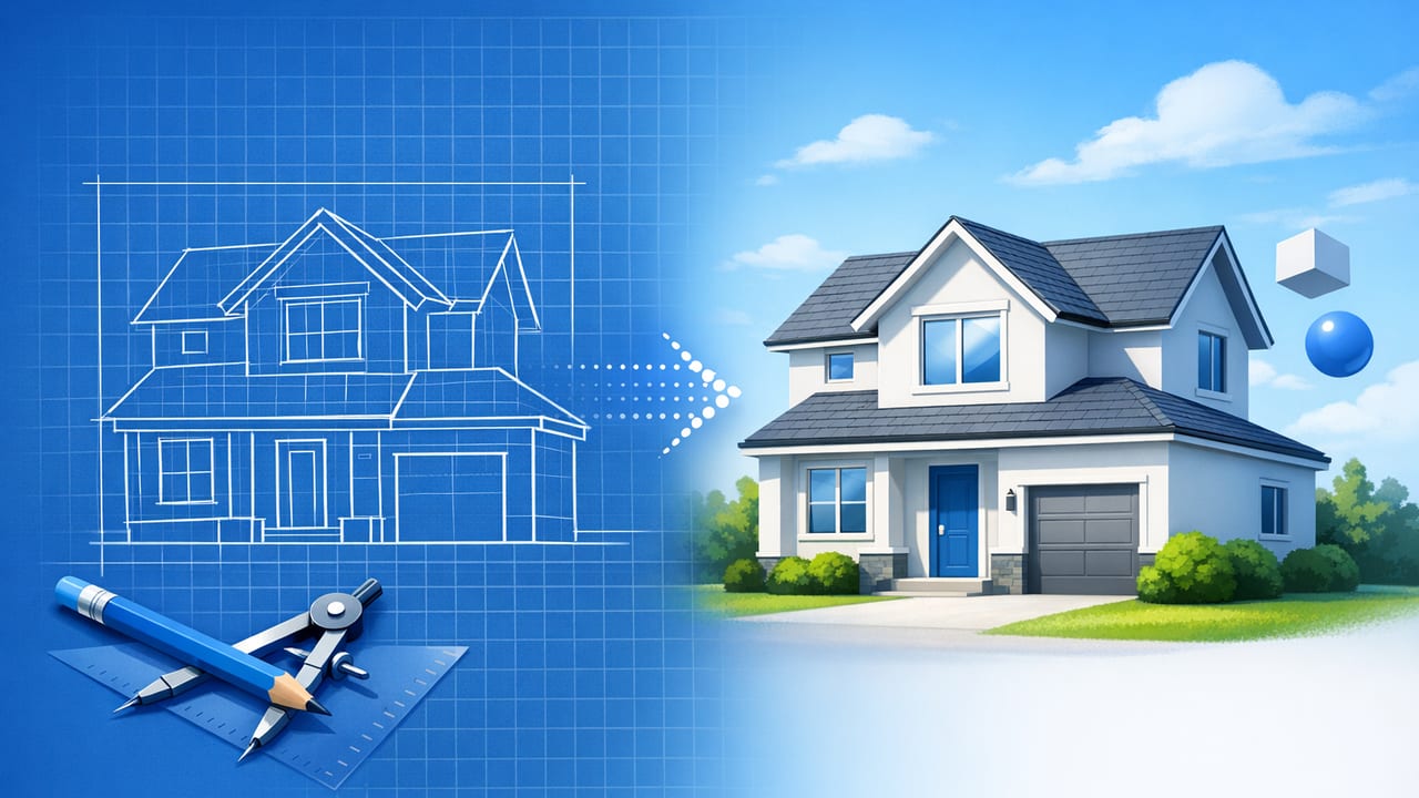
When you turn blueprint into 3d render, the goal isn’t just to “see it in 3D.” The real value is accuracy: the render should preserve dimensions, wall locations, room labels, door swings, and window placement closely enough that you can make renovation and layout decisions with confidence.
This guide walks through a practical, accuracy-first workflow—from preparing a black-and-white blueprint to validating scale, fixing common conversion issues, and generating clear 3D renders you can use for planning, proposals, or presentations.
What “accurate” means in a blueprint-to-3D workflow
Blueprints and floor plans vary widely: some are scanned, some are photographed, and some are exported from CAD. In 3D conversion, accuracy usually means:
- Correct scale (walls, openings, and room sizes match the plan)
- Consistent wall thickness and clean corners (no gaps, overlaps, or double lines)
- Openings placed correctly (doors/windows align with the plan)
- Readable labels and dimensions preserved where possible
- Faithful proportions even when some measurements are missing
Rule of thumb: A “pretty” render is easy to produce. A render that matches your plan well enough to avoid costly layout mistakes is the one that matters.
Step 1: Start with the cleanest blueprint image you can
Most conversion errors start before any 3D tool is involved. Spend a minute improving the input and you’ll save much more time later.
Best practices for scans or photos
- Scan straight (avoid angled photos; perspective skew distorts scale).
- Increase contrast so walls and text are clear against the background.
- Crop tightly to the plan area; remove title blocks if they confuse recognition.
- Use high resolution (blurry lines often become broken walls in 3D).
- Prefer black-and-white or clean grayscale; colored markup can be misread as walls.
Quick input checklist
- Are exterior walls clearly darker/thicker than interior walls?
- Are door swings visible (arc lines) and not smudged?
- Is at least one reliable dimension shown (overall width/length or a room dimension)?
Step 2: Lock in scale using a known measurement
Scale is the foundation. If scale is off by 5–10%, your furniture plan, cabinetry runs, and circulation clearances will all be wrong in 3D.
Choose one dependable measurement from the blueprint (for example, overall building width, or a clearly labeled room dimension). Then use it to calibrate the plan.
A simple way to compute scale from pixels (optional)
If you’re working with an image and want a quick sanity check, you can compute a pixels-to-feet (or pixels-to-meters) ratio using two points on a known dimension.
# Given:
# - known_length: real-world length (e.g., 12 ft)
# - pixel_distance: distance between two points in the image (e.g., 480 px)

scale = known_length / pixel_distance
# real_length ≈ pixel_distance * scale
You don’t need to code this in practice—many tools let you set scale by drawing a line and entering the real-world length—but thinking this way helps you verify the plan is not stretched or skewed.
Step 3: Understand what conversion tools “look for”
Whether you use an AI converter, a floor plan tracing tool, or a hybrid workflow, most systems rely on pattern recognition. They typically detect:
- Wall lines (parallel edges, consistent thickness)
- Room boundaries (closed shapes)
- Openings (gaps in walls, door swing arcs)
- Text (room labels, dimensions)
Knowing this helps you troubleshoot: if the blueprint has broken wall lines, messy hatching, or heavy annotations, the converter may interpret them as structural elements.
Step 4: Convert the plan—then immediately run an accuracy pass
After conversion, resist the urge to jump straight into materials and décor. First, validate the structure. Here’s a fast, repeatable process.
Accuracy pass (10 minutes that saves hours)
- Check overall footprint: compare exterior dimensions (or the longest known span).
- Verify 2–3 key rooms: measure a primary bedroom, kitchen width, and a bathroom.
- Inspect wall continuity: look for gaps, overlaps, or doubled walls.
- Confirm openings: doors centered correctly? windows on the right walls?
- Validate circulation: hall widths, door clearances, and pinch points.
Common issues and quick fixes
| Issue | What it looks like in 3D | Typical fix |
|---|---|---|
| Broken wall lines | Small gaps, rooms not enclosed | Reconnect segments; simplify noisy parts of the blueprint |
| Double walls | Two parallel walls where one should exist | Delete duplicates; ensure one consistent wall thickness |
| Misread door swings | Door placed on wrong side or wrong direction | Flip hinge side; snap door to correct opening |
| Incorrect scale | Furniture looks too big/small | Recalibrate using a known dimension and re-check key spans |
| Text interpreted as geometry | Random small “walls” or blocks | Remove artifacts; crop out title blocks/notes before converting |
Step 5: Add heights and architectural assumptions (carefully)
Most blueprints focus on plan view. To create a convincing 3D render, you’ll need vertical decisions. Use defaults unless the plan specifies otherwise, and document assumptions for stakeholders.
- Ceiling height: use what’s typical for your region/home type if not specified.
- Window sill and header heights: keep consistent across rooms for realism.
- Door heights: standard interior door height is a safe baseline unless noted.
- Stair geometry: if stairs appear, validate rise/run so the 3D model remains plausible.
If your goal is a renovation preview (not construction documents), it’s okay to keep these assumptions simple—just don’t let them distort the perceived proportions of the space.
Step 6: Use an AI room planner to test layout ideas faster
Once the structural shell is correct, an AI room planner can speed up decision-making by generating multiple furniture layouts or redesign directions while respecting the room boundaries you’ve validated.
Where AI planning helps most
- Living rooms: try multiple seating arrangements without manually dragging everything.
- Bedrooms: validate bed placement, walkway clearances, and dresser locations.
- Kitchens: explore work triangles and island clearances before committing to cabinetry.
- Empty-room staging: produce “move-in ready” visuals for listings or presentations.
Practical constraints to check (even with AI suggestions)
- Leave comfortable clearances around dining tables and sofas.
- Ensure doors can swing fully and aren’t blocked by furniture.
- Keep walkways logical between high-traffic points (entry → kitchen → living).
Step 7: Choose a render style that matches the decision you’re making
“3D render” can mean anything from a clean massing view to photoreal imagery. Pick a style based on the purpose.
Render styles and best uses
- Simple 3D massing: fastest way to confirm layout, walls, and proportions.
- Material mockups: good for comparing flooring, paint, cabinet colors.
- Photoreal interior: best when selling a concept to a client or household.
- Exterior refresh render: ideal for siding, trim, roof color, and curb appeal tests.
For renovation previews, clarity often beats realism. Crisp lighting, clean edges, and correct scale usually communicate better than heavy visual effects.
Blueprint-to-3D options: a realistic comparison
There are several ways to convert a blueprint to a 3D model/render. The right option depends on timeline, required precision, and your tolerance for manual work.
| Approach | Speed | Accuracy potential | Best for |
|---|---|---|---|
| Manual CAD/3D modeling | Slow | Very high | Construction-level modeling, detailed documentation |
| AI-assisted conversion + manual cleanup | Fast | High (with validation) | Renovation previews, early design exploration, presentations |
| Outsourced rendering service | Medium | Medium–high (depends on brief) | Marketing visuals when you can wait and provide clear notes |
Final QA: the “confidence checklist” before exporting
Before you export high-resolution 3D images for a proposal or share screenshots with a contractor, run this checklist:
- Scale verified against at least one overall dimension and two room dimensions
- All rooms closed (no open boundaries unless intentional)
- Doors/windows correct in count and approximate placement
- Major fixtures located (kitchen/bath elements in plausible positions)
- Heights reasonable (ceilings, doors, windows consistent)
- Exports labeled (option A/B, “existing vs proposed,” room names)
FAQ: turning a blueprint into a 3D render
Do I need every dimension on the blueprint?
No, but you need at least one reliable reference measurement to calibrate scale. More dimensions reduce ambiguity and help validate tricky rooms.
What if the blueprint is old or slightly distorted?
Old scans can warp. Use the largest known dimension to scale, then spot-check additional lengths. If multiple checks disagree, the image may be skewed—try rescanning or photographing more squarely.
Can I use 3D renders for construction?
Renders are excellent for visualization and decision-making, but construction requires code-compliant drawings and detailed specs. Treat 3D previews as a planning tool unless your workflow produces full documentation.
Wrap-up: accuracy first, then aesthetics
To successfully turn blueprint into 3d render, focus on input quality, scale calibration, and a quick structural validation pass before you explore design options. Once the model matches the plan, 3D renders become a powerful way to test renovation ideas, compare layouts, and communicate changes clearly—without wrestling with heavy software.
If you prefer an iPhone/iPad workflow, apps like Floor Plan to 3D & Home Redesign can help convert black-and-white plans into clean 3D visuals and support faster room-planning iterations.
