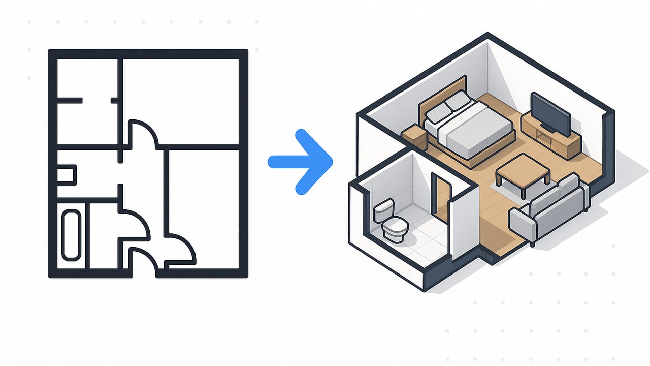
If you work with scanned drawings, PDFs from agents, or old plan sets, you’ve likely wondered how to turn black and white floor plan into 3D without losing accuracy. This guide walks you through a practical, end-to-end process: preparing the source plan, calibrating scale, choosing a conversion path, building the model, running quality checks, and exporting high-quality images for presentations or client approvals.
Before You Start: Prepare the Plan
Clean input makes the 3D output faster, cleaner, and more accurate. Spend a few minutes tuning the plan image before modeling.
- Scan or capture at the right resolution: 300–600 dpi for prints; set smartphone scans to “high” or “document” mode.
- Flatten and de-warp: Use a hard surface, avoid lens tilt, and correct skew in an image editor (Perspective/Skew tool).
- Increase contrast: Boost contrast so walls and text are crisp; remove shadows and stamp marks.
- Crop margins: Keep only the drawing extents and the title block (if it includes scale or dimensions).
- Remove clutter: Hide or mask furniture overlays if they obscure wall lines.
File formats to keep
Prefer non-lossy or high-resolution formats: PDF (vector or high-res raster), PNG, or TIFF. JPEGs are acceptable if saved at high quality. Retain the original file as a reference.
Establish True Scale
Accurate 3D depends on accurate scale. Even a clean PDF can be off if it was exported incorrectly or if the scan is skewed. Always calibrate.
- Find a known dimension: A labeled room width, a door opening (typ. 800–900 mm or 32–36 in), or a dimension string.
- Measure on screen: Use your modeling app’s ruler, or measure pixels in an image editor.
- Compute the scale factor: Apply it once at import, then lock it.
# Example: scale calibration from a known dimension
# Replace units to suit your workflow
known_real_length_mm = 4200
measured_on_plan_mm  = 84
scale_factor = known_real_length_mm / measured_on_plan_mm  # 50
# Multiply all plan measurements by 'scale_factor' to get real-world size
Working from a printed architectural scale? Typical scales include 1:50, 1:100 (metric), or 1/4" = 1'-0" (imperial). Validate by measuring two known spans; if both are correct, your plan is calibrated.
Choose Your Conversion Path
There’s no single “best” method. Your choice depends on time, accuracy needs, and software skills.
| Method | Best for | Speed | Accuracy | Learning curve |
|---|---|---|---|---|
| Manual CAD/BIM modeling (e.g., Revit, Archicad, SketchUp) | Complex projects, full control | Slow–Medium | High | Medium–High |
| Semi-automatic tracing over image | Renovations, interiors, mid-size spaces | Medium | High (with good calibration) | Medium |
| AI/mobile converter apps | Quick concepting, proposals, space planning | Fast | Medium–High (with QA) | Low |
How to turn black and white floor plan into 3D: A Step-by-Step Workflow
1) Import and align
- Import the cleaned plan as an underlay/background.
- Rotate so north/up is consistent, or align with a major wall.
- Set the image to a locked layer to avoid moving it accidentally.
2) Calibrate scale once
- Pick a clear dimension (e.g., a 4000 mm room width) and scale the underlay until your measurement tool matches.
- Check a second dimension across another room to confirm.
3) Trace structural walls
- Use wall tools rather than generic lines; set global wall thickness based on the plan or typical standards (e.g., 100–150 mm interior, 200–300 mm exterior).
- Trace centerline or finish face consistently. Note what the plan uses; consistency prevents area errors later.
4) Add doors and windows
- Place openings where symbols appear; use the plan’s tags for sizes when available.
- Set sill heights and head heights for accuracy in 3D views.
5) Define levels and heights
- Assign floor-to-floor and floor-to-ceiling heights (e.g., 2700 mm typical). Multi-story? Create levels for each story, then copy/align walls accordingly.
6) Model stairs and special elements
- Use riser/tread counts and plan arrows; verify total rise equals floor height.
- Curved walls or bays: model as arcs/splines; double-check radii.
7) Room tags and materials
- Define room boundaries to compute areas automatically.
- Assign basic materials (floor, wall paint, tile) to communicate design intent in 3D.
8) Furniture and circulation
- Add essential furniture to test circulation (900 mm min clearances are a good rule of thumb).
- Use lightweight proxy objects if performance lags; swap for detailed assets before final renders.
9) Lighting and cameras
- Set daylight sun angles by geo-location or north arrow; add key interior lights for realism.
- Create two to four consistent camera views: living overview, kitchen, bedroom, and a top-down axonometric.
10) QA checks before you render
- Compare room widths/depths against plan dimensions; allow a small tolerance (±1–2% for scan-based reconstructions).
- Verify door swings, window placements, and stair headroom.
- Check gross internal area (GIA) or net floor area against the plan’s schedule if given.
Interpreting Monochrome Linework
Black and white plans often rely on drafting conventions:
- Wall thickness: Thicker double lines usually mean structural or exterior walls; thinner lines are partitions.
- Doors: A gap with an arc indicates swing; dimension and hinge side matter for circulation.
- Windows: Often two close lines or breaks in walls; sills may be dashed.
- Levels: Look for elevation callouts; if absent, assume typical heights and note assumptions in your deliverable.
“Garbage in, garbage out” applies to 3D. Clear, contrasted inputs and proper scale save hours of rework.
Accuracy and Quality Assurance
Your goal is a 3D that’s faithful to the original. Adopt a predictable QA routine.
- Two-point scale check: Verify both horizontal and vertical spans to catch skewed scans.
- Diagonals: Measure a room diagonal; deviations reveal off-square geometry caused by import distortions.
- Area sanity check: Compute per-room areas and compare with any provided schedule.
- Openings audit: Count openings and compare to plan symbols to ensure none are missing.
- Tolerances: For concept visuals, ±1% is often acceptable; for tender drawings, aim tighter and trace from vector PDFs if possible.
Quick QA checklist
- Scale calibrated and locked
- All walls traced with consistent reference (centerline or finish)
- Doors/windows placed with correct sizes and heights
- Rooms named and areas verified
- Stairs comply with total rise; headroom checked
- Two to four standard camera views saved
Lighting, Materials, and Realism
Even simple materials dramatically improve comprehension.
- Walls: Neutral paint with slight roughness (R=0.78, slight bump) keeps focus on layout.
- Floors: Assign a single wood or tile for consistency when comparing options.
- Glass: Use physically based materials; enable thin-walled glass for windows to save render time.
- Sun and sky: Set a midday sun for clean shadows and repeatable comparisons.
Exporting for Print and Web
Match output to your use case: crisp for print, efficient for web.
| Output | Use case | Resolution | Notes |
|---|---|---|---|
| Top-down axonometric | Brochures, sales sheets | 300 dpi at final print size | White background, thin outlines |
| Perspective interior | Client concept reviews | 1920×1080 or 2560×1440 | Balanced exposure, neutral palette |
| Hero shot | Web/portfolio | 4K (3840×2160) | Enable soft shadows, clamp highlights |
| Plan overlay | QC comparison | Same size as underlay | Half-transparent walls for alignment |
For print, export PNG/TIFF with 300 dpi. For web, JPEG at 85–90% quality is efficient. Use consistent naming (Project_Area_ViewType_Size.png) for version control.
Troubleshooting Common Issues
- Plan is skewed: Re-import and correct perspective before scaling. A single degree of skew across large spans can create visible errors.
- Missing or ambiguous walls: Cross-reference notes and room labels; use typical thicknesses and flag assumptions.
- Curved geometry looks faceted: Increase segment count for arcs or use true curves if supported.
- Multi-level cut lines: If the original plan mixes floors, separate layers or mask unneeded levels before tracing.
- Doors swing into furniture: Adjust furniture placement; verify clearances around door arcs (700–900 mm preferred).
Privacy, Permissions, and Provenance
Always confirm you have the right to use the plan. If the file contains personal data or addresses, mask sensitive info in shared exports. Preserve an untouched original and document key assumptions (heights, materials, centerline vs finish) in your deliverables.
FAQ
Do I need the original CAD to achieve accuracy?
No. A high-quality black-and-white plan plus careful scale calibration yields reliable results. Vector PDFs help, but well-prepped scans can be equally accurate for visualization and planning.
What if the plan lacks dimensions?
Use a known standard (door width, stair tread depth) to approximate scale, then validate against multiple rooms. Clearly label any assumptions.
How long does it take?
Simple apartments can be modeled in under an hour with an AI-assisted workflow; complex multi-story homes may take several hours, especially when refining materials and lighting.
Putting It All Together
To turn black and white floor plan into 3D efficiently, focus on three pillars: clean input, verified scale, and disciplined QA. Choose the conversion path that fits your timeline and accuracy needs, trace consistently, set levels and openings carefully, and present with clear, repeatable views. With a repeatable workflow, your monochrome lines become an accurate, convincing 3D story—ready for decisions, budgets, and stakeholder buy-in.
Note: If you prefer a fast, mobile-first workflow that preserves layout proportions, the iOS app Floor Plan to 3D can convert black-and-white plans into navigable 3D and export high-resolution images for presentations.
