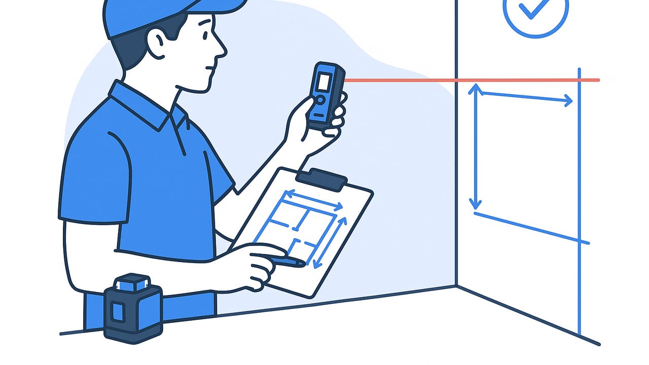
Whether you’re documenting an as-built, planning a remodel, or converting a paper plan to a digital model, learning how to trace walls with measurements is a foundational skill. Done well, it prevents costly rework, speeds up drawings, and produces geometry you can trust in 3D. This guide walks you through tools, setup, field techniques, quality checks, and how to translate traced outlines into reliable plans and models.
Before You Start: Tools, Units, and Accuracy Targets
Professional results come from consistent methods and the right gear. You don’t need everything on this list, but combining a few will raise your accuracy and speed.
- Laser Distance Meter (LDM) with ±1/16–±1/8 in (±1–3 mm) accuracy
- Tape Measure (25–30 ft / 8–10 m) for short runs and sanity checks
- Tablet + Stylus or graph paper and pencil for sketching
- Smartphone camera for annotated photos and room panoramas
- Bubble level or digital angle finder for slopes and roof pitches
- Chalk line and painter’s tape for temporary straight references
- Optional: iPhone/iPad LiDAR for quick room captures; tripod for steady shots
Pick an accuracy target that matches your use-case:
| Use Case | Recommended Accuracy | Notes |
|---|---|---|
| Space planning, furniture layout | ±1/2 in (±12 mm) | Focus on clear room sizes and openings |
| Kitchen/bath design | ±1/4 in (±6 mm) | Include appliance/fixture clearances |
| Millwork, tight-fit cabinetry | ±1/8 in (±3 mm) | Measure finish-to-finish; capture diagonals |
Measure Once, Reference Many: Establish Control
Before you trace a single line, define a stable reference so everything relates back to something known.
- Pick an origin. Choose a corner that’s accessible and visible from multiple rooms. Label it (0,0).
- Create axes. Choose one wall as your X-axis (0°). A perpendicular wall defines Y. Note a north arrow for orientation.
- Set level datums. Record floor elevation(s) and ceiling height(s) per room, plus any step downs or soffits.
- Check squareness. Measure a rectangle’s diagonals. If they differ, the space isn’t perfectly square—note this early.
Pro tip: Use long baselines and locate features by offsets from those baselines. It reduces cumulative tape-to-tape errors.
Step-by-Step: Trace Walls with Measurements
Follow this flow to capture a floor efficiently and minimize mistakes.
- Sketch the perimeter first. Draw a rough outline of the exterior or the unit boundary. Label rooms, key doors, stairs, and windows.
- Decide your wall reference. Are you tracing face-of-finish (paint to paint) or centerline of wall? For interiors, face-of-finish is most intuitive.
- Measure long runs, then break down. For each wall segment, record the total length. Then measure openings (doors, windows) and the distances between them. Work left to right consistently and annotate the direction.
- Record wall thicknesses. At several spots, measure wall thickness and note wall types (e.g., stud, masonry, party wall). See typical values below.
- Loop closure test. When you return to your starting point, add up your segment lengths. The difference between your final point and the start is your closure error. If it exceeds your tolerance, re-check suspect segments.
- Capture diagonals. In each room, measure at least one diagonal. This helps you reconstruct true angles and verify squareness in CAD.
- Locate columns, chases, and niches. Measure their offsets from the nearest two walls (triangulation). Photograph each with notes.
- Record heights. Ceiling heights, sill and head heights, beam drops, and stair riser/tread dimensions matter when you move to 3D.
Openings and Offsets: The Smart Order
To avoid accumulating error when you trace walls with measurements, dimension openings in a consistent order:
- From wall corner to the near jamb
- Clear opening width
- Jamb to next feature (return, niche, column), then repeat
Mark door swings and window types (e.g., single-hung, casement). Note finished dimensions: up to trim, or rough opening if walls are open.
Tracing Over Photos, Scans, or PDFs
If you have a printed or digital plan and need to re-trace walls with accurate scale, use this workflow:
- Import the image/PDF into your drawing app (CAD, vector tool, or a floor plan app).
- Set scale from a known dimension. Use a labeled dimension or measure a feature on site to calibrate. Lock the image layer to prevent drift.
- Correct skew. If the source is a phone photo, apply a two-point perspective correction so horizontal and vertical lines are true.
- Trace with snaps. Draw polylines for walls on a new layer. Keep ortho constraints on where appropriate; add angles when required.
- Assign wall thickness. Offset to represent real thickness, or use a wall tool that stores core and finish layers.
Always verify one or two lengths on the traced result against physical measurements. If the difference exceeds your tolerance, rescale and recheck.
Wall Types and Thickness: What to Trace
Knowing typical assemblies helps you sanity-check field notes and decide how to represent walls in plan.
| Wall Type | Typical Finish-to-Finish Thickness | Notes |
|---|---|---|
| Interior stud, 2x4 with 1/2 in drywall both sides | 4.5 in (114 mm) | Common in residential |
| Interior stud, 2x6 with 1/2 in drywall both sides | 6.5 in (165 mm) | Plumbing or acoustic walls |
| CMU (8 in block) with plaster/drywall | ~9.5–10 in (241–254 mm) | Varies with finish system |
| Party wall / demising (multi-layer) | 5.5–8 in (140–203 mm) | Confirm on site; fire-rated |
If you only measured finish-to-finish but your software builds walls by centerlines, set the correct thickness and offset half the thickness to maintain interior clear dimensions.
Curves, Angles, and Irregular Rooms
Not every wall is orthogonal. Use these techniques for nonstandard geometry:
- Angled walls: Measure two adjacent sides and the included diagonal; you can reconstruct the angle in CAD with the triangle.
- Curved walls (arcs): Measure chord length, arc height (sagitta), and offsets at quarter points. This uniquely defines an arc.
- Bay windows: Treat each face as a segment; measure each segment length and the offset from the main wall.
- Irregular polygons: Triangulate from a baseline: pick two known points and measure to each vertex.
Quality Control: Catch Errors Before They Multiply
Great tracing is mostly great QA. Bake these checks into your workflow:
- Closure tolerance: Keep perimeter closure within ±0.25% for general interiors (e.g., within 1 in over 35 ft).
- Redundancy: For long rooms, verify totals by summing segments and comparing to a single long shot with the LDM.
- Opposite walls: In rectangular rooms, opposite walls should match in length; investigate differences.
- Photo notes: Photograph each wall with sticky notes showing key dims. It’s faster than writing long descriptions.
- Units discipline: Stick to one unit system in the field notes. Convert later in the office.
A simple closure calculation you can jot down on site:
// closure_error = distance between start and end points after tracing the loop
// acceptable if closure_error <= max(0.25% of perimeter, 1 in)
From Traced Walls to a Reliable 3D Model
Once you’ve traced walls with measurements and verified them, moving to 3D is straightforward:
- Normalize your plan. Set a consistent wall reference (centerline or finish), thicknesses, and story heights.
- Add openings with elevations. Doors get head heights; windows get sill and head heights. Include swing/operation where it affects clearances.
- Assign levels and materials. Floors, ceilings, beams, and soffits need correct elevations for clash-free 3D.
- Export clean geometry. Purge stray lines. Use layers for walls, doors, windows, and structure so downstream tools can interpret correctly.
Perform a reality check by comparing a few room areas and key dimensions in 3D against your field notes. A fast visual sanity check often surfaces small but impactful mistakes.
Sample Field Notes Template (CSV)
Use this template to structure measurements and speed up data entry later:
room,feature,type,ref_wall,offset_from_ref,inches,notes
Kitchen,Perimeter,Wall,North,0,167.50,Start at NW corner
Kitchen,Door,Opening,North,36.00,36.00,Door 3068 LH, head 84
Kitchen,Window,Opening,East,52.25,48.00,Sill 36 head 84
Kitchen,Column,Obstacle,South,102.00,12.00,12x12 boxed out
Kitchen,Diagonal,QC,NA,NA,198.00,NE to SW diagonal
Frequently Asked Questions
Should I measure exterior-to-exterior or finish-to-finish?
For interior space planning and most remodels, measure finish-to-finish. Use exterior-to-exterior only if you’re coordinating structure or facade work, and then account for wall buildup to back-calculate interior clears.
How many diagonals do I need?
At least one per room, more for long or irregular spaces. Diagonals confirm true shapes and help correct small angle deviations when drafting.
Are LiDAR scans accurate enough?
Phone LiDAR is fast for context and rough geometry, typically within ±1–2% for room-scale measurements. Pair it with targeted LDM measurements for critical runs, openings, and QC.
What is the best way to handle stair measurements?
Record total rise, total run, number of risers and treads, tread depth, riser height, and width. Note headroom at the minimum point and any winders. In plan, trace the stair opening and direction of travel.
How do I avoid cumulative errors on long walls?
Measure both the total wall length and the sum of segments. If they disagree by more than your tolerance, re-check the shortest segments first—they’re easiest to misread.
A Quick Conversion Helper
If you need to convert field notes from feet-and-inches to millimeters (or vice versa), here’s a simple snippet you can adapt:
# Python: feet-and-inches string to millimeters
import re

def to_mm(s):
    # accepts formats like 12' 6 1/2" or 12'6" or 150"
    feet = 0
    inches = 0.0
    m = re.search(r"(\d+)\'", s)
    if m: feet = int(m.group(1))
    m = re.search(r"(\d+(?:\.\d+)?)\"", s)
    if m: inches = float(m.group(1))
    # support fractional inches like 6 1/2"
    m = re.search(r"(\d+)\s+(\d+)/(\d+)\"", s)
    if m:
        inches = float(m.group(1)) + float(m.group(2))/float(m.group(3))
    total_inches = feet*12 + inches
    return round(total_inches * 25.4, 1)

print(to_mm("12' 6 1/2\""))  # 3810.0
Common Mistakes to Avoid
- Mixing references: Switching mid-project from finish-to-finish to centerline will offset everything. Choose one and stick to it.
- Ignoring thickness: Tracing only centerlines without assigning real wall thickness leads to wrong clearances in 3D.
- No closure checks: Skipping perimeter closure often hides a single bad segment that throws off the whole plan.
- Scaling from unknown photos: Without a known dimension or calibration object in the photo, you’re guessing.
- Forgetting heights: Plans need Z-data. Capture ceiling heights, soffits, and step changes while you’re there.
Putting It All Together
To trace walls with measurements efficiently and accurately, think like a surveyor: establish control, capture long baselines, dimension features in a consistent order, and verify with diagonals and closure checks. Use your LDM for speed, a tape for tricky corners, and photos for context. Normalize wall references and thicknesses before you draft, and your plan will translate cleanly into 3D without surprises.
When you’re ready to visualize the result, a modern workflow can take you from a traced 2D plan to an accurate 3D representation in minutes. If you already have a black-and-white floor plan and want a quick, faithful 3D visualization to validate proportions and layout, the iOS app Floor Plan to 3D can convert your plan into a dimension-true 3D render suitable for proposals and client review.
