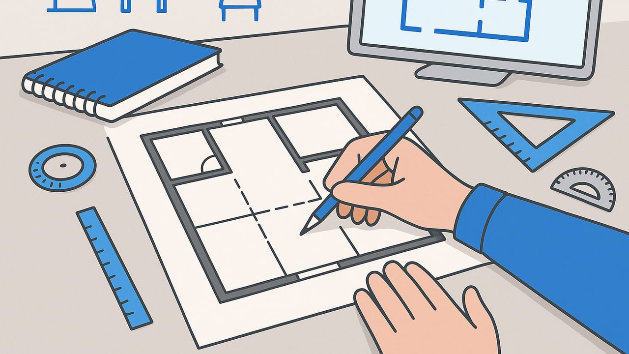
Floor plans are the language of space. Whether you are renovating a kitchen, planning a new build, or evaluating a listing, being able to read and draw floor plans with confidence saves time, money, and confusion. This guide covers the essentials: what floor plans show, common symbols, scale and measurement, field measuring, practical layout rules, clear annotation, quality checks, file formats, and a simple path from 2D to 3D visualization.
What a Floor Plan Shows (and What It Doesn’t)
A floor plan is a horizontal slice through a building, typically about 4 feet (1200 mm) above the floor. It shows walls, doors, windows, stairs, fixtures, and furniture from above. Good floor plans communicate spatial relationships, dimensions, and circulation at a glance.
What floor plans do not show: ceiling details (unless annotated), wall finishes, precise elevation heights, and the full complexity of structure and MEP unless noted. Use elevations and sections for vertical information; use reflected ceiling plans for lighting and ceiling layout.
Standard Floor Plan Symbols and Notation
Knowing the symbols turns a confusing drawing into a clear map. Here are common symbols you’ll encounter on most floor plans:
| Symbol / Notation | Meaning | Notes |
|---|---|---|
| Thick parallel lines | Wall | Heavier line = cut through; thin lines = surfaces beyond. |
| Break in wall with thin line | Window | Often dimensioned to centerline or rough opening; sill height noted. |
| Arc attached to rectangle | Door and swing | Arc shows swing direction; door size typically in inches/mm (e.g., 30″ or 762 mm). |
| Stair rectangle with arrows | Stairs | Arrow indicates direction up; number of risers sometimes listed. |
| Toilet/bath/vanity icons | Plumbing fixtures | Use manufacturer footprints for accuracy; clearances are critical. |
| Triangle or S with dashed lines | Switch and control | Dashed lines may show switch-leg to fixture locations. |
| Circle with rays | Ceiling light | Ceiling devices often shown on a separate reflected ceiling plan. |
| GFCI, duplex outlet symbols | Electrical outlets | Plan notes specify height and type (e.g., GFCI). |
| Dimension strings with ticks | Measurements | Overall, intermediate, and opening dimensions; read from exterior face or centerline depending on standard. |
| North arrow & scale bar | Orientation & scale | Verify both before measuring; prefer a graphic scale bar when printing. |
Scale and Dimensioning Essentials
Floor plans are drawn to scale so measurements translate reliably. Common architectural scales are 1/4″ = 1′ (imperial) and 1:50 (metric). Avoid guessing from printed drawings; always trust dimension strings or use a graphic scale bar.
Quick conversion formulas
- Imperial: At 1/4″ = 1′, 1 foot in real life equals 0.25 inches on paper. A 10′ room draws as 2.5″.
- Metric: At 1:50, real length divided by 50 equals drawing length in the same unit. A 4000 mm wall draws as 80 mm.
# Python helpers for common floor plan scales
# Imperial: scale like 1/4" = 1'
IN_PER_FT = 12
DRAW_IN_PER_FT_AT_QUARTER = 0.25  # 1/4" = 1'

def real_ft_to_draw_in(feet):
    return feet * DRAW_IN_PER_FT_AT_QUARTER

# Metric: 1:50, 1:100, etc.
def real_mm_to_draw_mm(real_mm, ratio=50):
    return real_mm / ratio

# Examples:
# 12' room at 1/4"=1' -> 3" on paper
# 3600 mm wall at 1:50 -> 72 mm on paper
Dimensioning best practices
- Dimension to faces of structure or centerlines consistently; note your convention in the legend.
- Chain dimensions logically: opening sizes, between openings, then overall.
- Include clear window and door schedules or tags keyed to sizes.
- Add critical heights in plan where relevant: sill heights, counter heights, stair rise/run.
Measuring Existing Rooms for Accurate Floor Plans
When no reliable plan exists, a field measure comes first. Accurate baseline data prevents compounding errors later.
Tools
- Laser measurer plus a tape for small spans
- Graph paper or a tablet with a sketching app
- Camera or phone for reference photos
- Level, small square, and a notepad of room IDs
Workflow
- Start with a rough bubble sketch of each level; label rooms and note door locations.
- Measure overall exterior dimensions if accessible, then work room by room.
- For each room: measure length, width, ceiling height, and wall thickness if visible.
- Record all openings: door width/swing, window width, height, and sill height.
- Locate utilities: outlets, switches, radiators, vents, plumbing stacks.
- Note irregularities: out-of-square corners, sloped ceilings, bulkheads.
- Cross-check: sum interior dimensions plus wall thicknesses against the exterior overall.
Pro tips
- Measure to consistent reference points (e.g., drywall face to drywall face).
- Capture at least one diagonal per room to confirm squareness.
- Photograph each wall as you measure it; annotate photos later if needed.
Layout Rules of Thumb You Can Trust
Floor plans shine when they support comfortable movement and use. These clearances help you validate layouts quickly:
| Element | Recommended Clearance | Notes |
|---|---|---|
| Main circulation path | 36″–42″ (915–1065 mm) | Narrow halls feel cramped & hinder moving furniture. |
| Door to adjacent wall | 4″–6″ (100–150 mm) | Prevents trim and handle collisions. |
| Door swing overlap | Avoid overlaps | Two doors should not clash; consider pocket doors. |
| Toilet center to wall | 15″ min (380 mm) | 30″ min (760 mm) clear width recommended. |
| Toilet front clearance | 24″ min (610 mm) | 30–36″ improves comfort. |
| Kitchen work aisle | 42″–48″ (1065–1220 mm) | 48″ preferred for two cooks. |
| Countertop height | 36″ (915 mm) | Adjust for user needs; islands may vary. |
| Bed side clearance | 24″–30″ (610–760 mm) | More space aids sheet changes. |
| Dining chair pullback | 36″ (915 mm) | Wall to chair back when in use. |
| Stair clear width | 36″ min (915 mm) | Check local codes for handrail and headroom. |
Always verify local codes; the figures above are comfort-forward, not a substitute for jurisdictional requirements.
Annotating Floor Plans for Clear Communication
Well-annotated floor plans answer questions before they’re asked.
- Room names and areas: Label each space (e.g., Bedroom 2) and consider an area schedule.
- Legends: Explain symbols, hatch patterns (e.g., new vs. existing), and line weights.
- Levels and datums: Indicate finished floor elevations for split levels or sunken rooms.
- Callouts: Use tags for doors, windows, and fixtures keyed to schedules.
- North arrow and scale bar: Always include both.
- Title block: Project name, date, drawing number, scale, and author for version control.
From 2D Floor Plans to 3D Visualization
Turning floor plans into 3D models helps you test sightlines, daylight, furniture fit, and materials before committing. Even a simple massing model can reveal conflicts that 2D drawings miss.
Basic 2D to 3D workflow
- Import the floor plan as an underlay; confirm scale using a known dimension.
- Trace structural walls first; extrude to story height (e.g., 8–9 ft / 2400–2700 mm).
- Add interior partitions, doors, and windows with correct head and sill heights.
- Place stairs, then large fixtures (kitchen, bath) using manufacturer dimensions.
- Rough in major furniture to test circulation; adjust clearances.
- Set cameras at eye height (about 5′-6″ / 1650 mm) for realistic views.
- Do a quick daylight check by setting sun angles (morning vs. afternoon).
Keep in mind: fidelity to the original floor plan matters. Model from true dimensions and verify that wall centerlines align across levels to avoid mis-stacking structure.
QA: Reviewing and Redlining Floor Plans
Before sharing, build a habit of objective checks. A quick redline session catches issues early.
- Print at intended scale or use a graphic scale bar on screen to audit key dimensions.
- Door swing audit: run your finger around each room and check for collisions.
- Path of travel: trace likely routes; ensure accessible widths and turning radii where required.
- Fixture fit: verify that appliance doors can open and maintain clearances.
- Dimension audit: are overall and partials consistent? Are critical heights listed?
- Clash scan: stairs vs. headroom; beams vs. door headers; plumbing vs. structure.
File Formats, Layers, and Sharing
Clear organization makes floor plans reusable and easy to coordinate.
- Formats: Use PDF for locked presentation, DWG/DXF for CAD exchange, and PNG/JPEG for quick markups.
- Layering: Separate structure, partitions, furniture, dimensions, and annotations onto distinct layers. Name layers consistently (e.g., A-WALL, A-DOOR, A-ANNO).
- Line weights: Heavier for cut elements (walls), lighter for items beyond, dashed for hidden.
- Scale bars: Include a graphic bar so recipients can verify scale on any printer.
- Export: Check that line weights, fonts, and hatches embed correctly in PDFs; include a legend sheet for non-expert viewers.
Common Mistakes in Floor Plans (and How to Fix Them)
- Inconsistent scale: Fix with a graphic scale bar and a note; re-scale the underlay before tracing.
- Missing dimensions: Add overall, then critical openings, then interior clearances. Prioritize what affects construction and furniture fit.
- Ambiguous door swings: Draw arcs and label handing. Consider pocket or barn doors where swings clash.
- Ignoring structure: Check that long spans have supports; align walls between floors for load paths.
- Overstuffed rooms: Start with furniture footprints from real products; maintain circulation clearances.
- Poor orientation: Add a north arrow early; re-balance daylight by swapping functions if possible.
- Uncoordinated MEP: Reserve space for ducts, stacks, and electrical panels; note access clearances.
A Simple Starter Template for Floor Plans
When beginning from scratch, a minimal template speeds consistency. Include:
- Title block with project info and revision table
- North arrow and graphic scale bar
- Layer set: walls, doors/windows, stairs, fixtures, furniture, dimensions, annotations
- Text styles for labels, dimensions, and notes
- Legends for symbols and hatch patterns
Good floor plans are less about drawing more lines and more about making fewer questions.
Practical Example: Verifying a Bedroom Layout
Imagine a 12′ x 10′ bedroom. Place a queen bed (60″ x 80″) centered on the 12′ wall. Provide 30″ clearance each side and 36″ at the foot. Include a 24″ nightstand per side. Check the swing of the entry door; if it conflicts with a closet door, change the closet to bypass doors. Add outlets: one each side of the bed and one near the door per code. Dimension overall, then the location of the bed centerline to walls, then door and window openings. This tiny exercise forces you to apply symbols, scale, and clearances in one pass.
When to Transition from Concept to Detailed Floor Plans
Early concept plans can be light on dimensions and heavy on adjacency and massing. As you approach construction or bidding, your floor plans should evolve to include precise dimensions, tagged elements, schedules, and notes that remove ambiguity. If you find yourself writing long emails to explain a plan, consider that a signal to add the clarification right on the drawing.
Final Thoughts
Floor plans are your clearest tool for turning ideas into spaces. Mastering symbols, scale, and a repeatable workflow helps you communicate intent, coordinate with collaborators, and avoid costly changes in the field. As you iterate, leverage 3D checks to validate proportions and sightlines; even quick models can reveal issues before they become problems. And when you need a fast visualization from black-and-white floor plans, the Floor Plan to 3D iOS app can convert your 2D layouts into accurate 3D renders you can evaluate and share.
