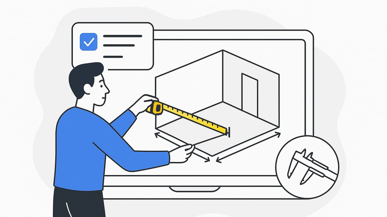
Getting scale right is the quiet superpower behind every trustworthy 3D layout. Whether you are validating a remodel concept, planning circulation, or preparing a client presentation, a model that measures true to scale underpins credible decisions. In this guide, you will learn a practical workflow to measure true to scale 3D layout projects, set clear tolerances, avoid common pitfalls, and verify accuracy with fast checks that work across mobile apps, CAD, and visualization tools.
What "true-to-scale" really means
In floor plan and interior modeling, true-to-scale means the 3D geometry preserves real-world distances and proportions within an acceptable tolerance. A door that is 900 mm wide in the plan is 900 mm wide in the model; a 4.8 m wall is not 4.7 m or 5.0 m after conversion. The model remains dependable for layout, feasibility, and dimensional reasoning.
Scale vs. accuracy vs. precision
- Scale: The ratio between model and reality (e.g., 1:50 on paper), or a direct unit match in digital models (1 unit = 1 mm).
- Accuracy: How close modeled distances are to the real dimensions.
- Precision: How consistently you can repeat measurements in the model.
In practical terms, for room planning and visualization, a good target is ±1% overall size accuracy (or better) and ±5 mm to ±10 mm precision on small elements, depending on project scope.
Before you start: clean inputs and set units
Most scale errors are introduced at the very beginning. Take a moment to normalize inputs and lock units early.
- Deskew and crop scans or photos of floor plans to remove perspective tilt.
- Use a known dimension visible on the plan (e.g., a dimension string or grid spacing). Avoid relying on "typical" sizes (like assuming a door is 36 in) unless you can corroborate with at least one explicit dimension.
- Set units (metric or imperial) before tracing or modeling. Changing units later can round values and introduce subtle offsets.
- Check for non-uniform scaling: If the plan was printed or photographed at an angle, X and Y may scale differently. Using two perpendicular reference dimensions helps detect and correct this.
Step-by-step workflow to measure true to scale 3D layout
- Import and align the plan
- Place the 2D plan on an orthographic or top-down canvas.
- Rotate so walls align with orthogonal axes where possible.
- Snap a known reference line (e.g., a 4000 mm room width) along the X or Y axis.
- Set the scale from two known dimensions
- Define a scale using a clearly labeled dimension (e.g., 5000 mm). If your tool supports it, define a second perpendicular reference to detect skew.
- Lock the scale. Refrain from free-scaling the plan image afterward.
- Trace walls correctly
- Know whether the plan dimension is to finish, centerline, or structure. This affects how you offset wall thickness.
- Use parametric wall tools with explicit thickness settings and heights.
- Insert openings with real sizes
- Doors and windows should use actual width/height, not placeholders.
- Mind the difference between rough opening and clear opening.
- Apply floor-to-ceiling and slab data
- Ceiling height impacts vertical fits (e.g., tall cabinets, glazing). Set global heights early.
- Place furniture by footprint
- Use items with editable dimensions. Confirm sofas, beds, and tables match spec sheets.
- Keep pathways clear; validate circulation early.
- Run measurement and diagonal checks
- Use the measure tool to verify at least five critical spans: two walls, a diagonal, and a few opening widths.
- Diagonal checks expose skew: if a rectangle’s measured diagonal deviates from theoretical, you may have non-uniform scale.
- Validate tolerances and freeze geometry
- Compare model values to the plan. If you exceed your tolerance threshold, fix before adding detail.
Typical wall thickness references
| Element | Finished thickness (metric) | Finished thickness (imperial) | Notes |
|---|---|---|---|
| Interior stud wall | 100–125 mm | 4–5 in | Varies by stud size and drywall |
| Exterior insulated wall | 200–350 mm | 8–14 in | Depends on climate and assembly |
| Masonry wall | 200–300 mm | 8–12 in | Check structural vs finish |
| Partition (lightweight) | 75–100 mm | 3–4 in | Commercial partitions can be thinner |
When a plan gives centerline dimensions, offset thickness equally on both sides. For finish-to-finish dimensions, ensure your wall tool is set to place the finish face on the traced line.
Tolerances that work in practice
Tolerances depend on the task. Visualization and interior planning can accept slightly larger tolerances than fabrication drawings. Here are pragmatic targets:
| Scope | Recommended tolerance | Examples |
|---|---|---|
| Room-level planning | ±1% of longest room dimension, min ±10 mm (±3/8 in) | Furniture fit, circulation checks |
| Whole-home adjacency | ±1% to ±2% | Bubble diagrams, zoning, path of travel |
| Joinery placement | ±5 mm to ±8 mm (±3/16 to ±5/16 in) | Cabinet runs, appliance clearances |
| Openings/doors | ±5 mm (±3/16 in) | Door swings, egress checks |
Pro tip: "Measure twice, model once—then verify diagonals." A diagonal mismatch is the fastest red flag for skewed scale.
Quick math: scale from two references
If your software allows two-point calibration, use it. If not, you can still sanity-check with simple math. Suppose a plan image shows a dimension labeled 5000 mm, and measuring that pixel span yields 1974 px. Your scale factor S (mm per pixel) is:
# Pseudocode for image-to-model scaling
known_length_mm = 5000
measured_pixels = 1974
S_mm_per_px = known_length_mm / measured_pixels  # ~2.532 mm/px

# A second perpendicular known length helps detect non-uniform scaling:
known_length2_mm = 3600
measured_pixels2 = 1418
S2_mm_per_px = known_length2_mm / measured_pixels2

if abs(S_mm_per_px - S2_mm_per_px) / ((S_mm_per_px + S2_mm_per_px)/2) > 0.01:
    warn("Potential skew or aspect distortion; deskew or re-calibrate X/Y.")
In practice, let the software handle calibration, but keep this logic in mind: two independent references enable you to catch distortions early.
Common pitfalls and how to fix them
- Printed plans scanned at the wrong scale: Printers may shrink/expand PDFs a few percent. Always trust the dimension strings over the title block scale. Calibrate to a labeled dimension, not the nominal 1:100 or 1/4 in = 1 ft noted on the sheet.
- Phone photos with perspective: Photograph plans square-on. If the app provides a deskew tool, align to four corners. Otherwise, crop generously and recalibrate using two perpendicular dimensions.
- Centerline vs finish confusion: Confirm which line you traced. If walls are too thick/thin after tracing, reassign the wall reference face (center/inner/outer).
- Openings set to rough sizes: Doors/windows pulled from a library may default to nominal widths. Edit to match the plan’s clear opening or finished dimension as required.
- Unit changes midstream: Switching from mm to inches late can introduce rounding. Lock units before modeling; if you must switch, re-verify critical spans.
- Curved or angled walls: Use segmented arcs as needed but confirm chord lengths with direct measures. Curves can amplify small scale errors over long spans.
Verification scenarios and quick tests
- Box test: Draw a rectangle that matches a room’s labeled width and length. Compare the model’s measured rectangle to the plan. Then check the diagonal; it should equal sqrt(width² + length²) within tolerance.
- Door swing sanity: Insert a typical 810–915 mm (32–36 in) door and verify clearances around furniture and corridors. If the swing clips objects that should be clear, re-check wall-to-wall spacing.
- Grid cross-check: If the plan uses a grid (e.g., 1200 mm spacing), overlay a matching grid in your software and compare alignments.
- Circulation widths: Validate key paths at 800–1000 mm (32–40 in) in homes or per local codes for commercial. Consistent shortfalls often trace back to a scale error.
Clearances that reveal scale issues
| Scenario | Target clearance | Why it matters |
|---|---|---|
| Sofa walkway behind seating | 900–1050 mm (36–42 in) | Comfortable circulation |
| Dining chair pull-back to wall | 900–1000 mm (36–40 in) | Avoids crowding |
| Kitchen work aisle (one-cook) | 1000–1200 mm (40–48 in) | Functional workspace |
| Bed sides (queen/king) | 600–760 mm (24–30 in) | Access and comfort |
If your model consistently undershoots these norms despite compliant plan dimensions, revisit calibration and wall reference faces.
Export and communicate scale
After verifying the model, preserve scale and clarity in exports:
- Embed a scale bar or include a few key measured dimensions on screenshots or renders used for decision-making.
- Export at high resolution for print or proposals so dimension callouts remain legible (e.g., 300 DPI for letter/A4).
- Note unit system and any known tolerances on the sheet if the deliverable informs layout choices.
A compact QA checklist
- Units set (mm or in/ft) before modeling.
- Two-point calibration completed on perpendicular dimensions.
- Wall reference face (center/inner/outer) confirmed.
- Door/window sizes match plan labels, not library defaults.
- At least five measurement checks, including one diagonal.
- Circulation and clearance checks pass without systemic offsets.
- Final tolerance within project target (e.g., ±1%).
Putting it all together
To consistently measure true to scale 3D layout models, treat scaling as a first-class step, not an afterthought. Calibrate against explicit dimensions, validate with diagonals, and confirm clearances that reflect real-world ergonomics. Lock units early, use parametric elements with editable sizes, and keep a simple QA routine you can apply in minutes. These habits turn a nice-looking render into a reliable planning tool.
If you prefer a mobile-first workflow that converts black-and-white floor plans into accurate 3D while preserving proportions and enabling high-resolution exports, consider trying Floor Plan to 3D. Used thoughtfully with the calibration and QA practices above, it can help you move from 2D lines to trustworthy, true-to-scale 3D layouts with confidence.
