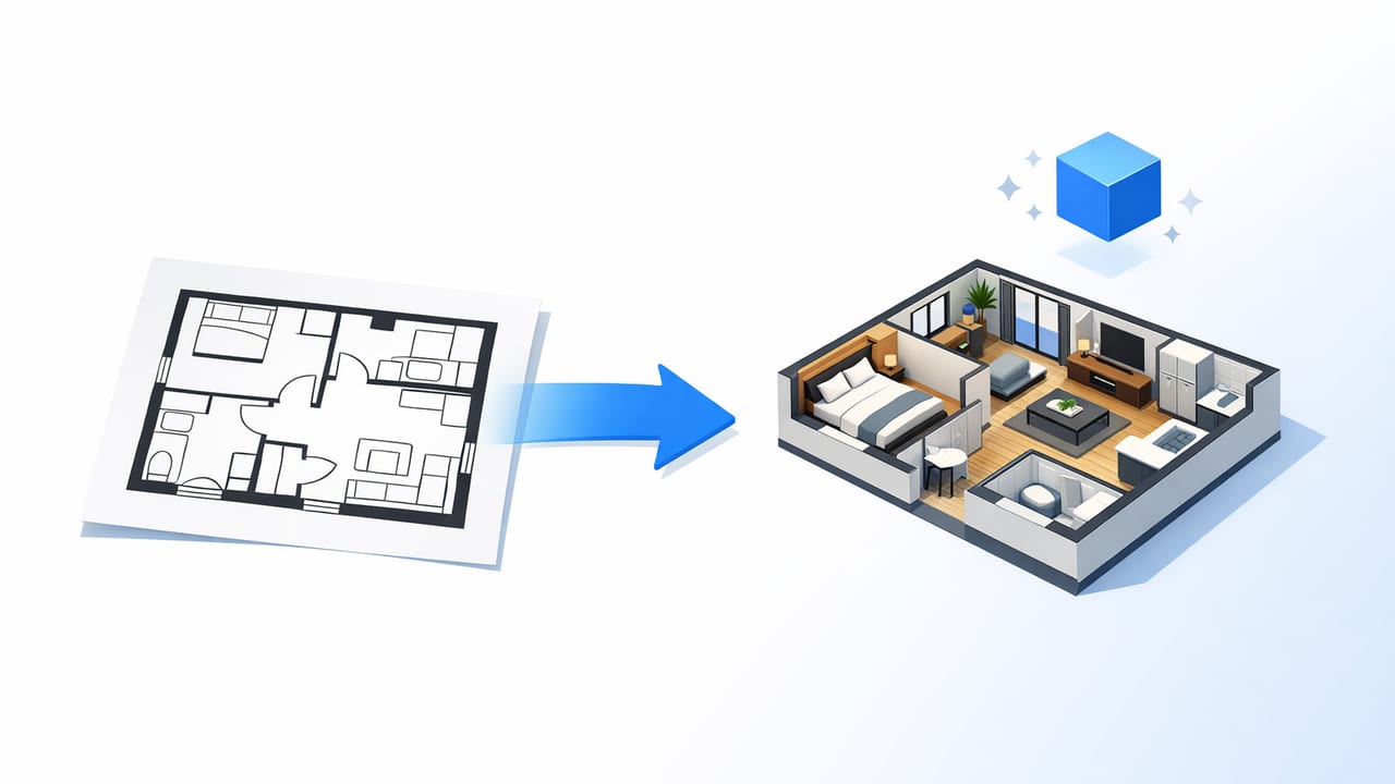
If you’ve ever tried to convert floor plan image to 3d, you already know the hard part isn’t making something that looks “3D”—it’s making something that stays true to the original plan. A slightly skewed scan, a missing dimension, or a wall line that’s too faint can cascade into a model that looks fine at a glance but fails when you start placing furniture, comparing remodel options, or presenting to stakeholders.
This guide breaks down a practical, accuracy-first workflow for turning a black-and-white 2D floor plan image (photo, scan, or PDF export) into a reliable 3D representation for AI home design, room planning, and architectural visualization. You’ll learn how to prep the image, set scale, avoid common conversion traps, and generate export-ready renders—whether you use AI-assisted tools, traditional CAD, or a hybrid process.
What “Convert Floor Plan Image to 3D” Really Means
Converting a floor plan image to 3D typically includes four technical steps:
- Extract geometry: identify walls, openings, and room boundaries from the image.
- Set scale: establish real-world units so the model is dimensionally meaningful.
- Build a 3D shell: extrude walls, add floors/ceilings, and cut doors/windows.
- Render or visualize: apply materials, lighting, and camera views for communication.
AI-based tools automate much of the geometry extraction and 3D construction. Traditional workflows (CAD/BIM) offer deeper control but require more manual tracing. Many professionals use a hybrid approach: AI for speed, then manual checks for accuracy.
Start with the Best Possible Floor Plan Image
The quality of your input image can determine whether conversion takes minutes or hours. Before you upload anything into a 3D rendering pipeline, aim for clarity and geometric consistency.
Image capture guidelines (photo or scan)
- Use a flat, evenly lit surface to avoid shadows that look like walls.
- Capture square-on: keep the camera parallel to the page. Perspective skew is a major cause of inaccurate wall angles.
- Prefer scans over photos when possible (higher uniformity and less distortion).
- Increase contrast so wall lines are distinct from annotations.
- Include at least one known dimension (e.g., a labeled wall length) to set scale later.
What to remove (or de-emphasize)
Most conversion errors happen when the system confuses annotations for geometry.
- Furniture symbols (beds, sofas), unless the tool explicitly supports them
- Hatching patterns, heavy textures, or dense notes
- Multiple floor levels on the same page
- North arrows, title blocks, legends (crop them out)
Pre-Processing: Make the Image “Machine-Readable”
Even if you’re using an app that accepts photos directly, basic pre-processing improves wall detection and reduces manual corrections.
Fast pre-processing checklist
- Crop to the plan boundary (remove margins and legends).
- Deskew so main walls align with horizontal/vertical axes when appropriate.
- Convert to grayscale and boost contrast.
- Sharpen lightly to strengthen faint lines.
- Export as PNG when possible to reduce compression artifacts (vs. low-quality JPEG).
Optional: simple preprocessing code (conceptual)
If you’re building an internal pipeline or testing image cleanup, this simplified OpenCV-style snippet illustrates common steps:
# Pseudocode for floor plan cleanup
img = load_image("plan.jpg")
img = crop_to_content(img)
img = deskew(img)
gray = to_grayscale(img)
contrast = adaptive_threshold(gray)   # separates ink from paper
clean = morphological_close(contrast) # closes small gaps in wall lines
save_image(clean, "plan_clean.png")
You don’t need to write code to benefit from these ideas—many editors (and some AI tools) apply similar operations under the hood.
Scaling: The Make-or-Break Step for Accurate 3D
A 3D model without correct scale is a picture, not a planning tool. To accurately convert floor plan image to 3d, establish scale before you invest time refining materials or furniture.
Best ways to set scale
- Use a labeled dimension (e.g., “12'-6"”) and calibrate the distance between those endpoints.
- Use a known standard only as a fallback (typical interior door widths, stair dimensions). This introduces assumptions.
- Validate across multiple spans: after scaling from one dimension, measure at least two other labeled lengths to confirm.
Common scaling pitfalls
- Printing distortion: scanned plans can be stretched slightly in one direction.
- Mixed units: some plans combine metric and imperial callouts.
- Wall thickness ambiguity: thick lines can hide the “true” wall centerline unless your tool handles it explicitly.
From 2D Lines to 3D Elements: Walls, Openings, and Levels
Most 3D conversion workflows follow the same structural logic: define walls, define openings, then define vertical parameters (heights).
1) Walls
When tools detect walls automatically, review these items:
- Continuity: are walls broken by small gaps from faint printing?
- Intersections: do T-junctions connect cleanly, or is there overlap?
- Thickness: is thickness consistent with the plan’s intent (interior vs exterior)?
2) Doors and windows
Doors and windows are frequent failure points because symbols vary widely. To reduce issues:
- Confirm swings: a wrong door swing can make a layout feel “off” even if dimensions are correct.
- Check window placement relative to corners and structural breaks.
- Watch for pocket doors and sliders—these are often misread.
3) Heights and levels
Many floor plan images don’t include vertical info. If you want believable 3D rendering results, define:
- Ceiling height (global default, then overrides by room if needed)
- Floor thickness (useful for section-like views)
- Window sill height and head height
Accuracy QA: A Practical Checklist (Table)
Before exporting images for a proposal or presentation, run a quick quality assurance pass. The goal is to catch “quiet” errors that will undermine trust later.
| Check | How to Verify | Why It Matters |
|---|---|---|
| Overall scale | Measure 3 labeled spans (not just one) | Prevents compounding size errors in furniture and circulation |
| Wall alignment | Confirm major walls are straight and intersections are clean | Avoids tiny gaps/overlaps that break room areas |
| Room closure | Ensure each room boundary forms a closed loop | Needed for accurate area calculations and flooring plans |
| Openings | Cross-check door/window locations vs. the 2D image | Impacts flow, furniture placement, and realism |
| Vertical assumptions | Document ceiling height and any deviations | Ensures consistent 3D proportions in views and renders |
AI vs Manual Modeling: Choosing the Right Approach
There isn’t one “best” method to convert a floor plan image to 3D—only the best fit for your constraints.
AI-assisted conversion (best for speed)
- Pros: fast turnarounds, minimal tracing, easy iteration for room planning.
- Cons: can misinterpret unusual symbols, curved walls, or low-quality scans.
Manual CAD/BIM modeling (best for control)
- Pros: precise control over layers, wall types, and construction logic.
- Cons: slower, requires expertise, less friendly for quick “what-if” exploration.
Hybrid workflow (often best for teams)
Use AI to generate the first-pass shell, then validate scale and fix edge cases manually. This is especially effective for architectural visualization where you need both speed and credibility.
Exporting 3D Renders That Communicate Clearly
Once your model is accurate, your outputs should match the use case: internal decisions, client presentations, real estate listings, or contractor discussions.
Recommended views to export
- Top-down 3D plan: best for comparing layouts quickly.
- Eye-level perspectives: best for spatial feel and furniture relationships.
- Dollhouse/isometric view: best for overall understanding of adjacency and flow.
Lighting and materials (keep it honest)
The purpose of architectural visualization is clarity first, beauty second.
Use neutral materials and consistent lighting to avoid “selling” a design with mood rather than communicating it. If you do apply materials, keep them consistent across iterations so comparisons are meaningful.
Troubleshooting: Common Problems and Fixes
Problem: walls are detected as double lines
Fix: Increase thresholding strength, simplify linework, or set wall centerlines manually if supported.
Problem: doors/windows are missing
Fix: Manually place openings using the plan’s symbols as reference; confirm that the image wasn’t over-processed (aggressive cleanup can erase thin arcs and window marks).
Problem: rooms aren’t recognized as rooms
Fix: Close gaps at corners, remove furniture symbols that break boundaries, and ensure continuous wall loops.
Problem: scale matches in one area but drifts elsewhere
Fix: Suspect scan distortion. Re-scan, correct perspective, or recalibrate using multiple known dimensions and adjust non-uniform scaling if your tool supports it.
FAQ
Can I convert a hand-drawn floor plan image to 3D?
Yes, but results depend on line consistency and clear symbols. Use high contrast, keep walls bold and continuous, and include at least one labeled dimension for scale.
What file type is best?
PNG is typically best for clean linework because it preserves sharp edges without heavy compression artifacts. High-quality PDF exports can also work well if you can import them directly.
How accurate can an AI conversion be?
With a clean plan and proper scaling, AI-based conversion can be highly usable for room planning and concept visualization. For construction-grade output, treat AI as a starting point and validate critical dimensions.
Putting It All Together: A Repeatable Workflow
- Capture a clean, square image (scan if possible).
- Crop and enhance contrast; remove legends and clutter.
- Convert with an AI or manual tool, generating walls and openings.
- Set scale using a known dimension; validate with multiple checks.
- QA geometry (closures, intersections, opening placement).
- Add heights and basic materials for legible 3D visualization.
- Export consistent views for presentations and comparisons.
Final Thought
The fastest way to convert floor plan image to 3d is not always the best way—especially if the 3D output will drive decisions. Prioritize a clean input image, lock scale early, and perform a short QA pass before you polish renders. If you prefer an iOS-first workflow for turning black-and-white plans into dimension-faithful 3D visuals, you can explore tools such as Floor Plan to 3D.
