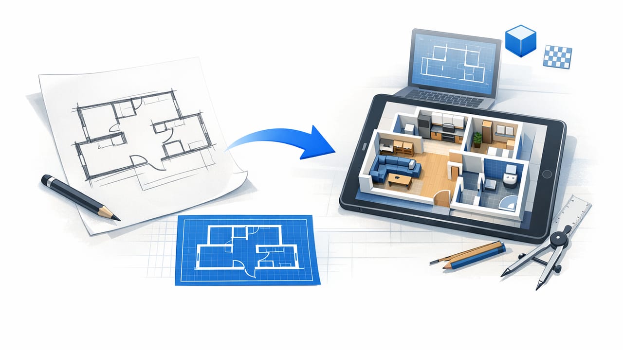
A good floor plan converter can turn a scanned drawing, PDF, or photo of a 2D layout into a usable 3D model for room planning, renovation decisions, and architectural visualization. A bad one can distort proportions, misread walls, or create a “pretty” render that quietly breaks scale—leading to wrong furniture fits, unrealistic circulation paths, and misleading client presentations.
This guide explains how floor plan conversion works, what “accuracy” really means in practice, and how to evaluate tools and workflows so your 3D output stays faithful to the original design.
What a floor plan converter actually does (and where errors come from)
Most conversion tools follow a pipeline that looks simple on the surface—upload a plan, get a 3D view—but several interpretation steps happen in between. Understanding them helps you predict and prevent mistakes.
- Image cleanup and normalization: deskewing, contrast adjustment, noise removal, and separating foreground lines from background texture.
- Line and symbol detection: identifying walls, openings, stairs, fixtures, and text labels.
- Topology reconstruction: turning detected lines into connected wall loops and room boundaries.
- Scale inference: using a stated dimension, scale bar, or user calibration to map pixels to real units.
- 3D extrusion and component placement: applying wall heights, thickness, and adding doors/windows as 3D elements.
Conversion errors usually happen in two places: mis-detection (a wall is mistaken for a cabinet line) and mis-scaling (the model is proportionally correct but the overall size is wrong). The best tools give you visibility and control over these steps, not just a single “magic” output.
The accuracy checklist: what to look for before you trust the 3D
When evaluating a floor plan converter, prioritize features that protect dimension truth. Use this checklist during trials.
1) Scale calibration you can verify
Look for at least one of the following:
- Known-dimension calibration: you click two points (e.g., ends of a 10 ft wall) and enter the real length.
- Automatic reading of dimension strings: the converter recognizes “12'-6\"” or “3800 mm” labels.
- Scale bar detection for architect sheets.
If a tool cannot explain how it determined scale, treat the model as conceptual only.
2) Wall thickness and corner logic
Accurate wall thickness matters for net room sizes and furniture clearance. Converters should handle:
- Consistent thickness across exterior vs interior walls (or allow per-wall adjustment).
- Clean corner joins without gaps/overlaps that create tiny “phantom rooms.”
- Curved and angled walls (even if simplified) without breaking the footprint.
3) Door/window placement you can edit
Openings are frequent failure points because symbol styles vary widely. Your converter should let you:
- Move and resize doors/windows after detection
- Flip door swing direction
- Set sill height and window type when needed
4) Evidence of room detection (not just extrusion)
Some tools extrude walls but never define rooms, which limits area calculations and room-by-room planning. Prefer converters that identify room regions and keep them editable.
Input quality: how to prep your plan for better conversion
Even strong AI benefits from clean inputs. Before uploading, spend 2–5 minutes on prep—often the difference between a quick correction pass and a full redraw.
- Use the highest-quality source available: export a PDF directly from CAD when possible; otherwise scan at 300–600 DPI.
- Crop to the plan boundary: remove title blocks, notes, and large legends if they overlap the drawing area.
- Increase contrast: walls should be darker than furniture lines and hatches. Avoid shadows from phone photos.
- Remove perspective distortion: if photographing, keep the camera parallel; use a document-scanner mode to flatten.
- Ensure at least one known dimension: a single labeled wall length enables reliable scaling.
Tip: If you only have a photo, take it in even lighting and include a ruler or known object length in-frame as a backup calibration reference.
A practical workflow: from 2D plan to dimension-true 3D
Use this workflow whether you’re planning a remodel, staging a listing, or creating a concept render for review.
Step 1: Import and set scale first
Before adjusting anything else, calibrate scale using a known wall length. Then verify it by measuring a second wall and comparing against the plan’s labeled dimension. If the second wall is off, fix scale now—don’t “correct later.”
Step 2: Validate the footprint (outer perimeter)
The exterior footprint drives everything: gross area, window placement, rooflines (if relevant), and room proportions. Inspect corners and long runs for:
- Broken lines causing missing walls
- Extra segments from text/annotations being misread
- Misaligned exterior walls after deskewing
Step 3: Confirm wall thickness assumptions
If the converter guesses thickness, confirm it matches your context (e.g., older masonry vs modern stud walls). Even a small thickness mismatch can change room clearances and door alignments in tight layouts.
Step 4: Place openings and fix swings
Openings affect circulation and usable wall space. Ensure doors don’t collide, and confirm window widths match the plan where possible.
Step 5: Add heights and levels (when needed)
Most floor plan converters assume a default ceiling height. If you’re planning cabinetry, lighting, or tall furniture, set a realistic height and check stair geometry and landings carefully.
Step 6: Furnish in “blocking mode” before styling
Use simple placeholders (bed, sofa, dining table) to validate fit and walking paths. Save materials and décor for the end—style changes are easy; fixing proportions is not.
Comparison table: conceptual vs accuracy-first conversion
| Feature | Conceptual Conversion | Accuracy-First Conversion |
|---|---|---|
| Scale handling | Auto-guessed, rarely explained | User-calibrated and verifiable |
| Wall connectivity | May leave gaps/overlaps | Clean joins, editable topology |
| Door/window detection | Basic symbols only | Editable placement, swing, sizes |
| Room areas | Not calculated or unreliable | Room regions defined and measurable |
| Best use case | Mood boards, early inspiration | Renovation planning, proposals, approvals |
Common pitfalls (and how to fix them fast)
Problem: “My 3D looks right, but furniture doesn’t fit”
Cause: incorrect scale or wall thickness assumptions.
Fix: recalibrate using a known dimension; verify two separate spans; then adjust wall thickness and re-check room widths.
Problem: “Interior walls are missing or merged”
Cause: low-contrast lines, heavy hatching, or furniture lines confusing detection.
Fix: re-upload a cleaned image (increase contrast, remove hatch layers if possible), or manually trace only the structural walls first.
Problem: “Doors/windows appear in the wrong place”
Cause: symbol style mismatch across plan sets.
Fix: lock the wall layout, then manually correct openings. Treat openings as a second pass, not part of footprint validation.
Lightweight validation: a quick measurement script idea
If you export coordinates (or can read measurements via an API), a simple sanity check is to compare several key spans against expected values. Here’s a tiny pseudo-example for validating error tolerance:
// Pseudo-code: validate measured spans against plan dimensions
const spans = [
  { name: "Living room width", measured: 3.58, expected: 3.60 },
  { name: "Hall length", measured: 4.92, expected: 4.90 },
  { name: "Bedroom width", measured: 3.01, expected: 3.00 }
];

const tolerance = 0.02; // 2 cm

for (const s of spans) {
  const error = Math.abs(s.measured - s.expected);
  if (error > tolerance) {
    console.log(`FAIL: ${s.name} off by ${error.toFixed(2)}m`);
  } else {
    console.log(`OK: ${s.name}`);
  }
}
This is optional, but it illustrates the mindset: treat conversion like measurement, not just visualization.
FAQ: floor plan converter questions that impact results
Is a floor plan converter accurate enough for construction?
Typically, no. Converted 3D models are excellent for space planning and concept visualization, but construction documents should be produced and verified in professional CAD/BIM workflows with surveyed dimensions.
What file type works best: PDF, JPG, or PNG?
PDF exports from CAD are usually best. If you’re using images, PNG preserves crisp line edges better than heavily compressed JPGs.
Can converters handle hand-drawn sketches?
Many can, but accuracy depends on line clarity and whether at least one dimension is provided. Expect more manual correction than with CAD exports.
How do I know if my 3D is “dimension-true”?
Calibrate scale using a known dimension, then verify at least two additional measurements in different directions (width and length). Also check one interior span (e.g., a bedroom width) to confirm wall thickness assumptions aren’t skewing net space.
Putting it all together
The best floor plan converter is the one that makes scaling explicit, keeps walls editable, and helps you validate measurements quickly. If you treat conversion as an accuracy-first workflow—calibrate, verify, then furnish—you’ll get 3D renders that support confident decisions rather than just attractive images.
If you want to experiment with an iOS workflow that converts black-and-white plans into 3D while prioritizing proportional consistency, you can explore Floor Plan to 3D as one option among many.
