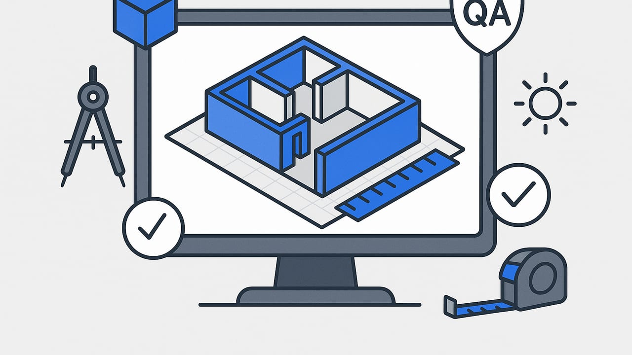
An accurate 3D floorplan does more than look good—it preserves proportions, tolerances, and spatial relationships so that every decision you make is grounded in reality. Whether you’re planning a remodel, staging an apartment, or preparing a presentation, accuracy ensures furniture actually fits, circulation flows, and budgets stay on track. This guide walks you through a practical, step-by-step approach to creating a reliable 3D model from a 2D layout, with measurement strategies, scale setup, quality checks, and export tips that work across tools.
What “accurate” means in a 3D floorplan
Accuracy is the degree to which your 3D model matches the physical space or the approved design intent. In practice, this means:
- Scale fidelity: The model is built to a known unit and scale, so dimensions read correctly.
- Dimensional tolerances: Deviations are within acceptable limits for decisions you’re making (e.g., cabinetry, furniture fit).
- Geometric correctness: Wall thicknesses, door/window sizes, and ceiling heights reflect actual conditions.
- Consistency: No conflicting measurements between rooms, levels, or sections.
For most residential projects, aim for ±0.5–1% overall dimensional accuracy and tighter tolerances (±5–10 mm or ±1/4–3/8 in) around doors, windows, and built-ins.
Inputs that drive an accurate 3D floorplan
Your 3D model’s accuracy depends on the quality of your inputs. Use one or more of these:
- Measured sketch: A hand-drawn plan annotated with dimensions. Include wall thicknesses, door widths, swing directions, window sill heights, and ceiling heights.
- Existing architectural drawing: A black-and-white plan with scale and dimensions. Verify a few critical measurements on site when possible.
- Laser measure: Use for long runs, diagonals, and ceiling heights. Cross-check room diagonals to confirm square corners.
- Photo or scan of the plan: If importing as a background image, verify scale using a known dimension and lock it before tracing.
Pro tip: Measure long dimensions twice using different reference points (e.g., wall face vs. baseboard edge). If they disagree, re-measure and resolve before modeling.
Set scale and units the right way
Scale is the foundation of an accurate 3D floorplan. Get it right first, not last.
- Choose units: Work consistently in either metric (mm, cm) or imperial (inches, feet). Avoid mixing.
- Calibrate an imported plan: If you’re tracing over a plan image, pick a long known dimension (e.g., total wall length) and scale the image to match precisely.
- Lock the base: Once scaled, lock the underlay to prevent accidental stretching.
- Check against a second dimension: Confirm with another known length to catch non-uniform scaling or skewed scans.
Build the shell: walls, thickness, and alignment
Walls are your datum. Errors here cascade into every room and furniture layout.
- Wall centerline vs. face: Decide whether you model to centerlines or to finished faces. For interiors, finished faces keep furnishings honest; for structural alignment, centerlines may be better. Don’t mix within the same model.
- Wall thickness: Typical residential interior walls range 90–120 mm (3.5–4.75 in). External walls can be 140–300 mm (5.5–12 in) or more, depending on materials. Model the real thickness if known.
- Orthogonality: Use perpendicular constraints or ortho snapping when tracing. Verify diagonals; a room that is out-of-square by more than 15 mm per 3 m (roughly 3/16 in per 10 ft) should be noted.
- Stacked floors: If modeling multi-level spaces, align stair openings and structural walls vertically using shared reference axes.
Openings matter: doors, windows, and heights
Small errors at openings can derail kitchen or bath plans. Capture these carefully.
- Doors: Note width, thickness, and swing. Common widths are 710–910 mm (28–36 in). Include clearances behind doors for trim and hardware.
- Windows: Record width, height, sill height (from finished floor), and head height. In 3D, sill/head heights influence light and sight lines more than you might expect.
- Ceiling heights: Model floor-to-ceiling height for each room and note bulkheads, beams, and soffits. Mark sloped ceilings with start/end heights.
Aim for an accurate 3D floorplan with data-driven tolerances
Use tolerances appropriate to your scope. This table summarizes practical targets for residential work:
| Element | Recommended Tolerance | Metric | Imperial | Notes |
|---|---|---|---|---|
| Overall length/width | ±0.5–1% | ±5–10 mm per meter | ±1/16–1/8 in per foot | Verify across long runs and diagonals |
| Room dimensions | ±10 mm | ±10 mm | ±3/8 in | Controls furniture fit |
| Wall thickness | ±5 mm | ±5 mm | ±3/16 in | Impacts door/window placement |
| Door/Window rough openings | ±5–8 mm | ±5–8 mm | ±3/16–5/16 in | Critical for cabinetry/trim |
| Ceiling height | ±5–10 mm | ±5–10 mm | ±3/16–3/8 in | Affects tall furniture and glass |
Furnish for function: clearances that keep you honest
Even with perfect scale, a layout fails if circulation is tight. Keep these clearance rules in mind:
| Use Case | Minimum Clearance | Comfortable Clearance |
|---|---|---|
| Walkway behind sofa or chairs | 760 mm (30 in) | 915–1000 mm (36–40 in) |
| Dining chair to wall/obstacle | 915 mm (36 in) | 1000–1070 mm (40–42 in) |
| Bed side clearance | 610 mm (24 in) | 760–915 mm (30–36 in) |
| Kitchen work aisle (one-cook) | 915 mm (36 in) | 1065–1220 mm (42–48 in) |
| Door swing clearance | Door width + 50 mm (2 in) | Door width + 100 mm (4 in) |
Place furnishings in 3D and orbit around them at eye level (about 1.6 m / 5 ft 3 in) to confirm sight lines and walkability. Use ghosted or wireframe overlays to visualize door swings and chair pull-out zones.
10-minute QA routine for an accurate 3D floorplan
- Scale spot-check: Measure two long, unrelated spans in the model. Compare to the plan. If off by more than 1%, rescale before proceeding.
- Diagonal check: Confirm squareness for at least two key rooms by checking diagonals.
- Openings audit: Verify a sample of door and window dimensions and placements along a common wall.
- Heights pass: Inspect ceiling heights, soffits, and beam drops in section/elevation views.
- Fixture fit: Test-fit largest items: fridge, tub, sofa, bed. Confirm clearance around them.
- Level alignment: If multi-story, drop section lines to ensure stairs and openings align.
- Render sanity check: Produce a quick clay render (no textures) to ensure geometry, not materials, is telling the story.
Lighting, materials, and the perception of accuracy
Lighting and textures don’t change measurements, but they can distort how space is perceived. Bright, uniform lighting can make small rooms feel larger, while heavy textures can visually shrink surfaces. For clarity during QA:
- Use neutral materials and a clay or white model pass for dimension checks.
- Set the camera to 35–50 mm focal length to minimize wide-angle distortion in rooms.
- Include a scale bar or dimension overlays in at least one exported view when accuracy matters to stakeholders.
Common pitfalls (and fixes) that derail accuracy
- Mixed units: If you imported a metric plan into an imperial project (or vice versa), dimensions will drift. Fix by resetting project units and rescaling the underlay using a known dimension.
- Skewed scans: Photos taken at an angle produce trapezoidal distortion. Re-scan from directly above or use software with perspective correction before tracing.
- Assumed wall thickness: Using defaults can misalign door/window centers. Measure or infer from known rough openings and update the wall type.
- Unmodeled soffits: Missing bulkheads make tall furnishings appear to fit. Add soffits and beams early to anchor vertical clearances.
- Overreliance on textures: Wood grains and tiles can create visual scale illusions. Validate with dimensions and section cuts.
Export settings that preserve accuracy
Presentation matters—don’t let compression or scaling mislead your audience.
- Resolution: For print at A3/Tabloid, export 300 DPI; for screens, 1920–2560 px on the long edge is typically sufficient.
- Aspect ratio: Choose 16:9 for slides, 3:2 or 4:3 for prints. Keep consistent across views.
- Dimensions and scale bars: Include at least one annotated plan or an unobtrusive scale bar so viewers can verify size.
- Camera metadata: Label views with focal length and approximate eye height to communicate perspective integrity.
- File formats: Use PNG for line clarity; JPEG at 90% quality for smaller files; TIFF for print workflows.
Workflow example: from black-and-white plan to accurate 3D
- Collect inputs: Black-and-white 2D plan with at least two known dimensions. Add notes for ceiling heights and any slopes.
- Import and calibrate: Bring the plan into your tool, scale with a long known dimension, lock the underlay.
- Trace walls to finished faces: Apply correct wall thickness types and align corners orthogonally.
- Add openings precisely: Enter numeric widths, heights, and sill/head heights. Verify at least one per wall.
- Set levels and ceilings: Model floor elevations, soffits, and beams. Add stair geometry if applicable.
- Place key fixtures: Kitchens, baths, appliances, beds, and wardrobes using manufacturer dimensions.
- Run QA: Check two spans, diagonals, and a openings sample. Produce a clay render for sanity.
- Style and export: Add materials and lighting. Export with a scale bar and dimensions on at least one plan view.
Simple dimension logging (optional)
Keeping a lightweight dimension log helps track changes and spot drifts. A simple CSV works:
Element,Location,Intended,Measured,Variance,Notes
Wall,Living North,6500 mm,6488 mm,-12 mm,Within tolerance
Door,Bed 1 Entry,820 mm,824 mm,+4 mm,OK
Window,Kitchen East,1200x1050 mm,1196x1052 mm,-4/+2 mm,OK
Ceiling,Hallway,2700 mm,2692 mm,-8 mm,Check soffit
Review the log at milestones to ensure the model remains within your targeted tolerances.
FAQ: Building an accurate 3D floorplan
How accurate should my model be?
For concept planning, ±1% overall and ±10 mm around openings is usually enough. For fabrication or built-ins, tighten to ±3–5 mm and corroborate on site before ordering.
Do photorealistic textures improve accuracy?
No. They improve realism, not measurement fidelity. Use neutral materials during QA; add photoreal textures after geometry is verified.
What’s the best way to handle irregular rooms?
Measure all sides and at least one diagonal. If walls aren’t perfectly parallel, record two widths at different points and model the taper explicitly.
Final checks: make accuracy visible
- Include dimension strings on plans and key elevations in your deliverables.
- Provide one orthographic top-down image and two perspective views at realistic focal lengths.
- Add a legend that lists units, scale, and any known tolerances or assumptions.
When you present not just visuals but also the data that underpins them, stakeholders trust the model—and the decisions that follow.
If you prefer a streamlined path from a black-and-white floor plan to a scaled, navigable model, the iOS app Floor Plan to 3D can transform 2D layouts into faithful 3D renders while preserving dimensions and proportions, with exportable high-resolution images for proposals and presentations.
