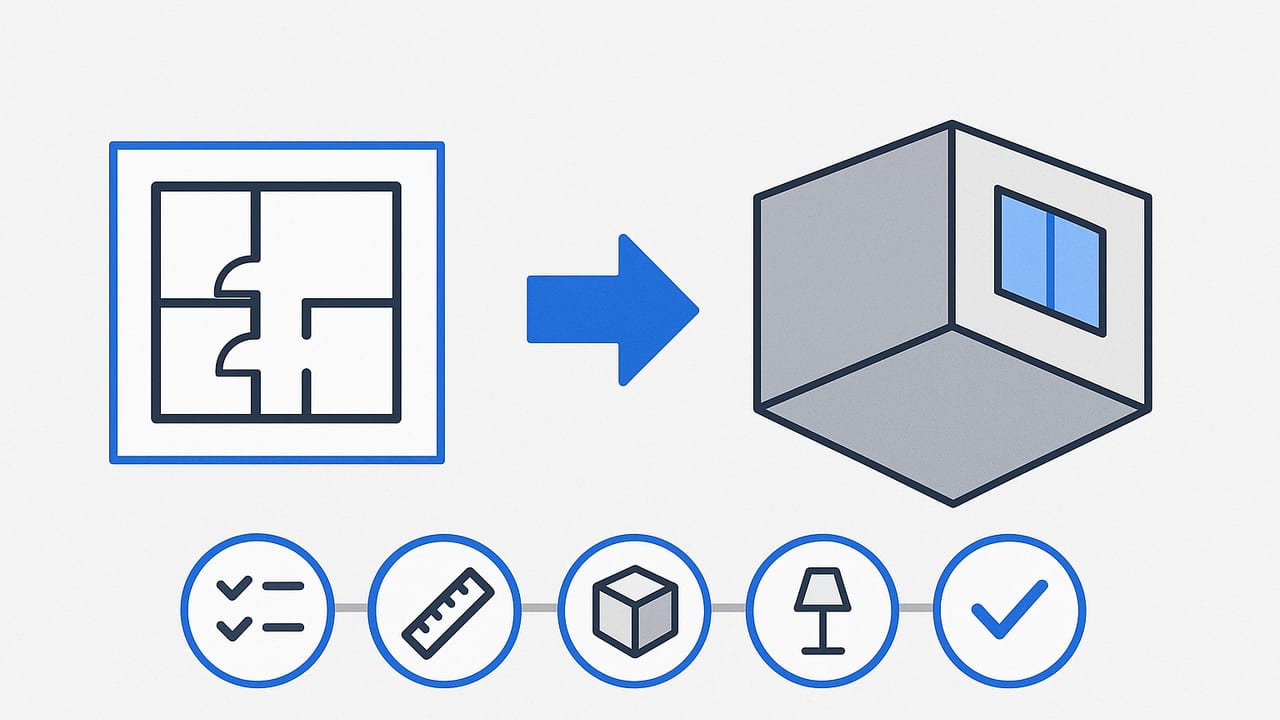
Converting a floor plan to 3D is one of the fastest ways to validate layouts, communicate design intent, and spot practical issues before construction or a remodel begins. Whether you are a homeowner planning a kitchen upgrade or a designer streamlining client presentations, a reliable floor plan to 3D workflow helps you move from lines on paper to believable, dimensionally correct spaces you can explore and iterate.
This guide covers the essentials: how to prepare a 2D plan, choose the right conversion method, scale and model accurately, and produce clear visuals that non-technical stakeholders understand. You will also find tips to avoid common accuracy pitfalls, a comparison of approaches, and a compact checklist you can reuse on any project.
What “Floor Plan to 3D” Really Means
Turning a 2D plan into a 3D model isn’t just about extruding walls. It involves translating symbols, dimensions, and relationships into a spatially coherent scene with correct scale and realistic materials, lighting, and camera perspectives. Key concepts include:
- Scale calibration: Align the drawing’s pixel or page units to real-world meters or feet.
- Semantic mapping: Recognize walls, doors, windows, stairs, fixtures, and tags (room names, dimensions) so they become 3D objects.
- Levels & heights: Set floor-to-floor, ceiling, sill, and lintel heights to keep vertical proportions true.
- Materials & lighting: Apply finishes and light sources that tell the story of volumes, daylight, and mood.
Prepare the 2D Plan: A Clean Input Saves Hours
Garbage in, garbage out. Before you import a floor plan, ensure it is clear, legible, and properly scaled.
- Use a high-resolution source: 300 dpi or better for scans; avoid blurry phone photos. If photographing, shoot straight-on, well-lit, and parallel to the page to reduce distortion.
- Crop and deskew: Remove margins and use a perspective/deskew tool to square the plan. A skewed plan introduces silent errors later.
- Confirm a known dimension: Identify a labeled length (e.g., a 3000 mm room) or door width you trust.
- Clean up clutter: Hide or delete annotations that are not needed: furniture scribbles, revision clouds, or duplicate dimensions.
- Check units: Verify whether the plan is in millimeters, centimeters, or inches; mixing units is a classic cause of scale drift.
Choosing a Conversion Approach
There’s no single best path from floor plan to 3D. Your decision depends on time, skill level, and the fidelity you need.
| Approach | How it Works | Pros | Cons | Best For |
|---|---|---|---|---|
| Manual CAD/BIM modeling | Import plan, set scale, model walls, openings, structure, fixtures | Highest control and accuracy; robust documentation | Steep learning curve; time-intensive | Professional design, permit drawings, detailed coordination |
| Semi-automatic tracing | Vector-trace walls and openings; extrude with presets | Faster than fully manual; decent accuracy | Requires cleanup; quality varies with input | Small studios, fast concept validation |
| AI-assisted conversion (mobile/desktop) | Upload image; AI interprets walls/doors; outputs 3D scene | Fastest path to a navigable 3D; beginner-friendly | Occasional misreads; needs accuracy checks | Homeowners, quick iteration, client previews |
| Photogrammetry of printed plan | Reconstructs geometry from multiple photos | Rapid context capture | Not designed for line drawings; alignment issues | Supplementary, not primary workflow |
The Core Workflow: Floor Plan to 3D in 8 Steps
- Import and calibrate scale. Use a known dimension on the plan to set the scene scale. If your software measures the drawn length as 2.36 m but the labeled dimension is 2.50 m, apply a scale factor of 2.50 / 2.36 ≈ 1.059. This ensures all subsequent work is proportionally correct.
- Trace or auto-detect walls. Model walls with correct thickness. Typical interior walls range 90–120 mm (3.5–5 in); exterior walls vary by climate and construction.
- Add openings and structure. Insert doors, windows, columns, beams, and stairs with accurate sizes and sill/lintel heights. Check swing orientation and clearance arcs for doors.
- Set levels and heights. Define floor-to-floor, ceiling height, and slab thickness. Maintain consistent stories if multi-level.
- Tag spaces. Name rooms and set intended use (kitchen, bath). Use this metadata to drive fixture standards and lighting defaults.
- Place fixtures and furniture. Start with minimum clearances: 900 mm circulation around dining tables, 1000–1100 mm kitchen work aisles, 760–915 mm beside beds. Use dimensioned assets to avoid scale creep.
- Apply materials and lighting. Use neutral, PBR materials first; add area lights for windows and a few practicals. One HDRI plus a key area light often gives 80% of the realism with minimal setup.
- Frame cameras and export. Capture top-down 3D, eye-level perspectives, and a hero shot. Export high-resolution stills and, if available, an interactive view.
Accuracy Checks at Each Stage
- Scale tolerance: Keep within ±1% for concept, ±0.5% for cabinet/fixture fit checks.
- Door logic: Verify swings and egress clearances. A mis-swing often signals a flipped plan.
- Grid sanity: Spot-check three non-parallel dimensions; if mismatch is systematic, recalibrate scale.
- Ceiling height consistency: Compare to standard fixtures (e.g., 2.4–2.7 m ceilings with common pendant drops).
Rule of thumb: If three spot-checks agree, your scale is likely correct. If two disagree, recalibrate before detailing.
Dimension Preservation: Common Failure Modes and Fixes
- Skewed scan: Parallel lines converging? Deskew in an image editor before import. Even a 1–2° skew can become a 50–60 mm error across a room.
- Perspective distortion from phone photos: Re-shoot straight-on or use a perspective correction tool. Avoid wide-angle lenses that bend edges.
- Unit confusion: mm vs. cm or inches. Set project units immediately and label them in your file name (e.g., “Apartment_A1_mm”).
- Wall thickness approximations: If plan omits thickness, assume local construction norms and note your assumption. Reconcile later with as-built data.
- Rounding drift: Small rounding on each component compounds. Lock critical dimensions (kitchen carcasses, appliance niches) early.
Quick Math: Calibrating Scale from an Image
When your software lets you measure a line on the imported plan, you can set a precise scale factor with a simple formula:
// Pseudocode for image-based scale calibration
measured_on_plan = 2.36   // meters, measured from the image
real_world_value = 2.50   // meters, labeled on the plan
scale_factor = real_world_value / measured_on_plan  // 1.059...
applyScale(scale_factor)
After applying the factor, re-measure a second reference line to verify accuracy. If both agree within tolerance, continue.
Visualizing Layout Options Fast
Once your model is scaled, you can explore alternatives quickly without rebuilding from scratch:
- Variants: Duplicate scenes (Plan A/B/C) to swap island sizes, sofa orientations, or bedroom wardrobes.
- Adjacency mapping: Check sightlines and proximity. Keep noisy zones (laundry) buffered from quiet zones (bedrooms).
- Color zoning: Use color-coded materials to test program clarity before committing to finishes.
Sample Adjacency Matrix (2-Bed Apartment)
| Space | Living | Kitchen | Bed 1 | Bed 2 | Bath |
|---|---|---|---|---|---|
| Living | — | Preferred | Buffer | Buffer | Nearby |
| Kitchen | Preferred | — | Neutral | Neutral | Nearby |
| Bedrooms | Buffer | Neutral | — | — | Nearby |
Use such matrices to justify design moves when presenting options.
Render Quality vs. Speed: Where to Invest Time
You don’t need a perfect photoreal render to make solid planning decisions. Focus on the 20% of effort that gives 80% of clarity:
- Lighting: One HDRI for overall ambience + a sun/area light for window directionality + a few practicals (pendants, sconces).
- Materials: Neutral, mid-gray walls; slightly rough floors; avoid overly glossy defaults. Realistic roughness values do more than high-res textures.
- Cameras: Eye height ~1.6 m, 24–28 mm equivalent focal length for interiors; avoid extreme wide angles.
- Ambient occlusion: A subtle AO pass helps read edges and depth without heavy computation.
// Minimal render preset (concept)
render.samples = 256
render.denoise = true
lighting.envHDRI = "overcast_01.hdr"
lighting.sun.intensity = 1.2
camera.fov = 65  // ~24–28mm equivalent
materials.enablePBR = true
post.AO.intensity = 0.2
Deliverables Clients Understand
Package outputs that communicate layout, scale, and feel:
- Top-down 3D axon: Communicates adjacency and circulation instantly.
- Eye-level perspectives: One hero view of main space, plus two functional views (kitchen working triangle, bath clearances).
- Annotated overlays: Add dimensions for key fits (island clearance, door swings).
- High-resolution stills: 3000–4000 px on the long edge for print or proposals.
Mobile-to-Desktop Workflow Tips
Many teams start on mobile for speed, then refine on desktop. To keep the handoff smooth:
- Lock scale metadata: Export with embedded units and a reference line marked with real-world length.
- Name layers consistently: Walls, openings, fixtures, furniture, annotations; avoid generic names.
- Export options: Prefer formats that preserve geometry and materials (e.g., USDZ, GLTF/GLB, FBX) alongside a PDF of the original plan.
- Include a readme: Note assumptions: wall thickness, ceiling height, any deviations from the original plan.
Frequently Asked Questions
How accurate can an automatic floor plan to 3D conversion be?
For concept planning, expect ±1–2% with a clean plan and a verified scale. With manual checks and corrections, you can achieve ±0.5% accuracy, sufficient for layout and clearance validation. For fabrication or permits, verify against field measurements.
What if my plan is skewed or low resolution?
Deskew the image before import and use the highest-resolution source available. If text and dimension lines are unreadable at 200–300% zoom, re-scan or re-photograph the plan.
Can I handle multi-storey projects?
Yes. Model each level with consistent reference heights. Align stair openings and check cumulative tolerances at structural cores to maintain vertical alignment across floors.
Do I need photorealism to make decisions?
No. Clear geometry, accurate scale, and sensible lighting reveal more than highly detailed textures. Photorealism is helpful for client marketing, but planning decisions rely on proportions and clearances.
Which formats should I export?
For visualization and AR, GLTF/GLB or USDZ are compact and portable. For DCC pipelines and collaboration, FBX and OBJ are common. Always include a PDF or PNG of the original plan and a brief note on units and assumptions.
A Compact Checklist You Can Reuse
- Clean input: high-res, deskewed, uncluttered.
- Calibrate scale from a trusted dimension, then verify a second one.
- Model walls, openings, levels; tag spaces early.
- Place dimensioned fixtures; respect circulation and clearance norms.
- Light simply but intentionally; keep materials realistic and neutral.
- Export top-down 3D and two to three clear perspectives at high resolution.
- Document assumptions; keep units consistent end to end.
Done well, moving from floor plan to 3D brings clarity, prevents costly mistakes, and builds consensus. Whether you prefer desktop software or a fast mobile workflow, the key is to start with a clean plan, lock scale, and verify at every step. For users who like an on-the-go approach, an iOS option such as Floor Plan to 3D can turn black-and-white plans into dimensionally faithful 3D previews and export high-resolution images for proposals and presentations.
