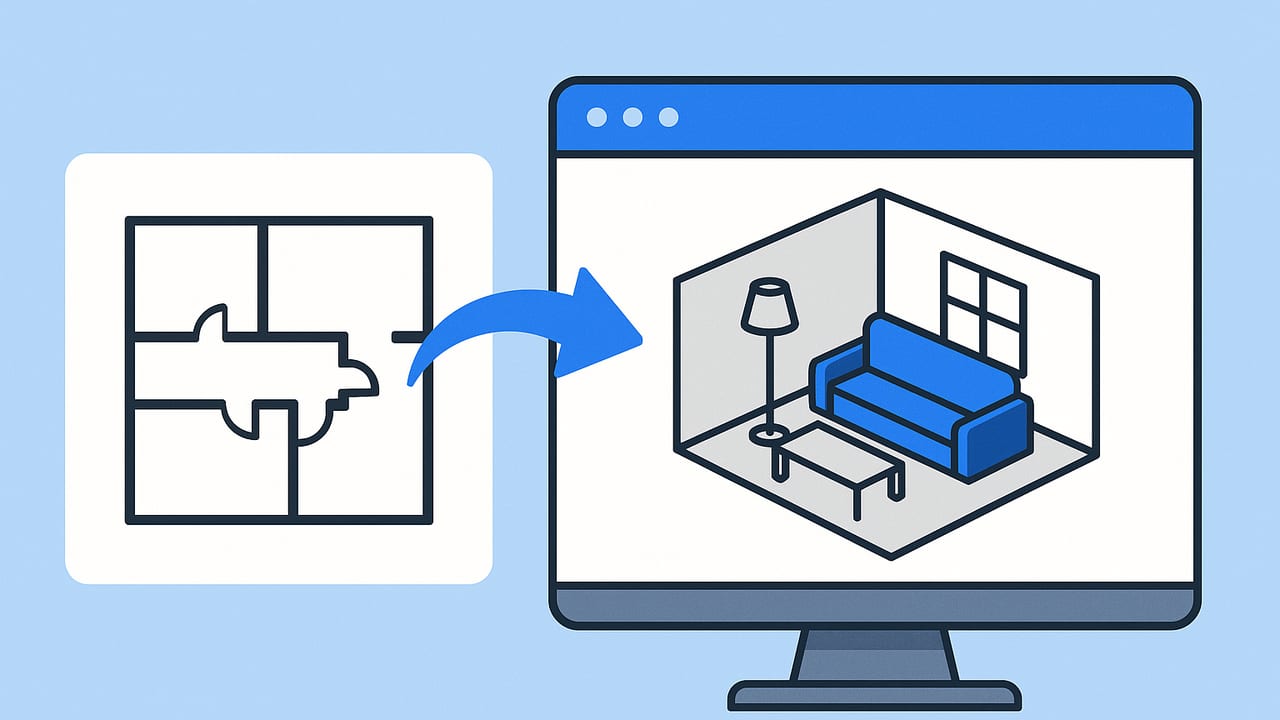
Turning a flat drawing into a believable space is one of the fastest ways to test ideas, spot mistakes, and communicate design intent. Converting a floor plan to 3D brings scale, light, materials, and furnishings into a single view so you can make decisions with confidence. This guide walks through the essentials: preparing your plan, preserving dimensions, modeling efficiently, and exporting visuals that help stakeholders understand the space.
What a floor plan to 3D conversion really means
At its core, a floor plan is a set of dimensions and adjacencies. The goal of moving from floor plan to 3D is not just to produce a pretty image but to maintain spatial fidelity while adding vertical information and materials. The key ingredients include:
- True scale: Your 3D walls, openings, and furniture must match the plan’s geometry, not just approximate it.
- Heights and levels: Walls, ceilings, sills, and stair risers introduce the vertical dimension that a 2D plan can’t show.
- Openings and circulation: Doors, windows, and clearances dictate how a room works in real life.
- Materials and light: Surface reflectance and daylight affect perceived size and mood.
- Viewpoints: Strategic cameras help you evaluate sightlines and furniture fit.
Measure twice, model once. The biggest speed boost in 3D is avoiding rework by nailing scale and structure early.
A step-by-step workflow from 2D to 3D
1) Prepare the plan
Start with the cleanest possible input. If you have a paper plan, scan it at 300–600 DPI. Remove handwritten notes, arrows, or title blocks that can confuse tracing. Boost contrast so walls read as solid, continuous lines. If the plan includes a bar scale or a single known dimension (e.g., a 10 ft room width), you can set scale precisely later.
2) Set the scale
Everything downstream depends on this step. If your plan is to scale, calibrate using either a known dimension or the bar scale. If the plan is a photo, account for lens distortion by standing directly over the page and aligning the edges before capturing.
Quick method: Measure a known line in the image (in pixels or mm on screen) and compute the scale factor.
# Simple scale factor helper (pixels to real units)
# Example: a 1200 px line equals 4000 mm in reality
pixels = 1200
real_mm = 4000
scale_factor = real_mm / pixels  # mm per pixel

# To get real size of any measured pixel length:
px_length = 350
real_size_mm = px_length * scale_factor
print(real_size_mm)
Use consistent units (mm or inches) and avoid rounding early. Keep at least 1 decimal place for inches or 1 mm precision.
3) Trace core structure
Trace exterior walls first, then structural interior walls, and finally partitions. Maintain wall centerline or wall face consistency throughout. If your software offers snapping, turn it on to lock orthogonal walls and corners. Enter wall thickness explicitly (e.g., 4.5 in or 115 mm).
4) Add openings
Place doors and windows at the correct widths and positions. Set heights such as door head, door leaf thickness, and window sill height. If the plan shows swings, match them so clearances and circulation render correctly.
5) Define heights and ceilings
Set the story’s floor-to-floor and ceiling height. If there are soffits, bulkheads, beams, or dropped ceilings, model them now to avoid later clashes with tall furniture or lighting.
6) Materials and finishes
Assign basic materials early to check reflectance and perceived space. A high-reflectance paint can brighten a small room; dark floors absorb light and may require stronger fixtures. Use realistic textures and scale them correctly (e.g., 6 in plank width for hardwood) to avoid visual distortion.
7) Furnish with true dimensions
Populate the space with dimensionally accurate items. Do not rely on generic placeholders if you’re validating fit. Check manufacturer dimensions or standard sizes:
- Queen bed: 60 x 80 in (1524 x 2032 mm)
- Standard sofa (3-seat): ~84 x 36 in (2134 x 914 mm)
- Dining chair: seat height ~18 in (460 mm), push-in depth ~18–20 in (460–510 mm)
- Counter depth: 24 in (610 mm); island aisle clearance: 42–48 in (1067–1219 mm)
8) Lighting: daylight and artificial
Set geographic location and orientation for sun studies if your tool supports it. For artificial light, place a few key fixtures first (ambient + task) and check shadow softness. Use IES profiles when available for realistic distributions.
9) Cameras and views
Establish 2–3 consistent vantage points per room: entry view, primary seating view, and an overhead axon or top-down. Keep eye height around 5 ft 6 in (1.65 m) for natural perspective. Lock focal lengths to avoid ultra-wide distortion.
10) Review and iterate
- Check door swings and collision with furniture.
- Confirm egress widths and minimum pathways.
- Verify stair headroom and landing sizes if present.
- Re-check critical dimensions after any scale or plan change.
Choosing the right method: manual modeling vs smart tools
Different projects call for different workflows. Here’s how popular approaches compare:
| Method | How it works | Strengths | Watch-outs | Best for |
|---|---|---|---|---|
| Manual modeling in CAD/BIM | Import plan as an underlay, trace walls, add components | High control, precise geometry, BIM data | Steeper learning curve, slower for simple rooms | Complex homes, renovations, documentation |
| Room planner with plan import | Upload plan, set scale, auto-detect lines | Fast setup, easy furnishing and visualization | May need cleanup on unusual shapes | Concepts, quick client visuals |
| AI-assisted conversion | App analyzes a floor plan image and builds 3D | Fastest from plan to 3D; preserves layout | Confirm wall thickness and heights; refine details | Early-stage planning, options testing |
| LiDAR/scan to model | Capture existing space and generate geometry | Great for as-built conditions | Requires site access; reflective surfaces can misread | Retrofits, verifying existing dimensions |
Accuracy pitfalls (and how to avoid them)
- Scaling drift: If a long wall in the model doesn’t match the plan, your scale is off. Recalibrate using two distant points to average out distortion.
- Wall thickness assumptions: Plans rarely print thickness labels clearly. Use typical thicknesses for your region or cross-check door widths to infer wall type.
- Curved or angled walls: Use arc tools and snap to tangents. Avoid approximating curves with short segments; it breaks trim and furniture alignment.
- Stairs: Confirm riser count and total run. A typical riser is 7–7.75 in (178–197 mm), tread 10–11 in (254–279 mm). Maintain consistent rise/run.
- Ceiling conflicts: Tall wardrobes and pendant lights can clash with beams or sloped ceilings. Cut sections to verify clearances.
- Wrong door swings: A mirrored swing can block a critical pathway. Cross-reference the plan’s swing arcs.
Clearance math that keeps layouts comfortable
Use these common targets when evaluating your 3D layout:
- Primary circulation: 36 in (915 mm) clear
- Bed sides: 24–30 in (610–760 mm) minimum
- Dining table to wall: 36–44 in (915–1118 mm) to pull chairs comfortably
- Work triangle (kitchen): each leg 4–9 ft (1.2–2.7 m)
- Toilet centerline to side obstruction: 15–18 in (381–457 mm)
- Shower interior: 30 x 30 in (762 x 762 mm) minimum, 36 x 36 in preferred
In 3D, test these with bounding boxes or dimension overlays so clearances remain visible even when materials distract the eye.
Lighting and material choices that affect perceived size
- Reflectance (LRV): Walls with higher light reflectance value make rooms feel larger. Keep ceilings lighter than walls for a lift effect.
- Specularity: Highly glossy floors can cause glare bands; a satin finish often reads better in renders.
- Daylight direction: Side lighting reveals texture; backlighting silhouettes forms. Show both to evaluate finishes and furniture massing.
- Consistent white balance: Mixed CCT lighting (2700K + 5000K) can make materials look off. Match fixture color temperatures.
Speed tips for moving from plan to 3D faster
- Start with structure only: Lock scale, walls, and openings before adding finishes or decor.
- Use asset libraries: Save parametric doors, windows, and furniture you trust dimensionally.
- Name and layer: Group by room (e.g., Living_Walls, Living_Furniture) to toggle views quickly.
- Templates: Keep a project template with default materials, sun settings, camera heights, and output sizes.
- Batch viewpoints: Create a default set of camera angles for every project so comparisons are apples-to-apples.
A quick QA checklist before sharing
- Scale verified against two known dimensions
- All doors and windows placed with correct size and swing
- Stair rise/run checked; headroom confirmed
- Ceiling heights and soffits modeled
- Furniture dimensions checked against manufacturer specs
- Primary pathways meet clearance targets
- Materials scaled correctly (tile size, plank width)
- Daylight orientation accurate; artificial lights labeled
- At least three consistent camera views per room
- Exported images include room name and scale note if needed
Export settings that help decision-making
- Resolution: 2000–3000 px on the long edge is typically crisp for screens and PDFs.
- Aspect ratio: 16:9 for presentations; 4:3 for tablets; square for social snapshots.
- Overlays: Lightly annotate critical dimensions or add a small scale bar on technical views.
- Comparisons: Export A/B options at identical camera positions for unbiased review.
Frequently asked questions
Can I convert a photo of a plan into 3D?
Yes, as long as you can set an accurate scale. The cleaner the lines and the more orthographic the photo, the better the result. AI-assisted tools can accelerate this from a simple black-and-white plan.
How accurate can a floor plan to 3D conversion be?
For conceptual planning, expect near one-to-one accuracy if you calibrate scale correctly and input true wall thicknesses. For construction-level documentation, use CAD/BIM with dimensioned plans.
What if my plan is not perfectly to scale?
Use two distant known dimensions to compute an average scale, or remodel using entered dimensions rather than tracing. Avoid scaling from very short lines, which exaggerates error.
Putting it all together
Moving from a floor plan to 3D is about preserving what matters: dimensions, adjacencies, and realistic constraints, while layering on believable light and material context. Start simple: convert one room, validate scale with two key measurements, add accurate furniture, and test a few viewpoints. As you get comfortable, expand to full homes, daylight studies, and option sets.
If you prefer a fast, mobile-first approach, there are iOS apps that analyze black-and-white plans and build true-to-layout 3D models you can refine and export. One example is Floor Plan to 3D, which uses AI to keep dimensions and proportions faithful while letting you visualize rooms and export high-resolution images for proposals.
