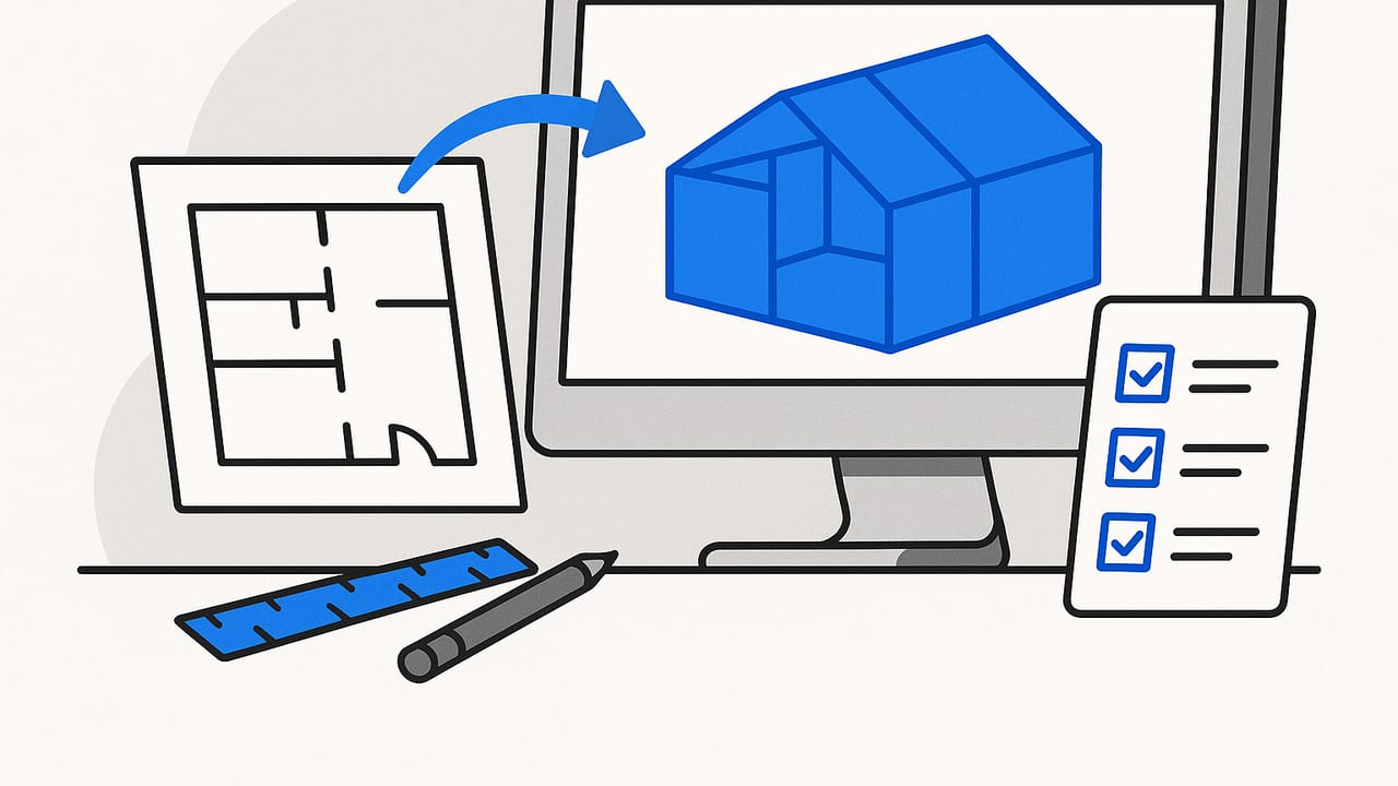
A floor plan converter turns flat, 2D drawings into interactive 3D spaces you can measure, walk through, and present. Whether you are a designer validating a concept, a contractor reviewing scope, or a homeowner planning furniture, the converter you choose is only half the story. The other half is your workflow: how you prepare inputs, set scale, assign heights, export, and verify accuracy. This playbook walks you through a practical, end-to-end process to get consistent results from any floor plan converter.
1. Start with the right inputs
Your floor plan converter can only be as accurate as the files you feed it. Begin by assessing source quality, file type, and legibility. Pay attention to line clarity, labels, and the presence of a printed scale or at least one known measurement. If you are starting from a phone photo of a plan pinned to a wall, correct perspective and contrast before conversion.
Raster vs vector at a glance
| Input type | Typical source | Key risks | Best practices |
|---|---|---|---|
| Raster: JPG, PNG, TIFF | Camera scans, emailed images | Skew, low DPI, faint lines | Scan at 300 to 600 DPI, deskew, increase contrast |
| PDF (raster or vector) | Architect sets, agent brochures | Unknown scale, embedded images | Check if selectable vectors; extract page at 100 percent |
| Vector: DWG, DXF, SVG | CAD exports | Unit mismatch, missing fonts | Confirm units, purge, flatten to a clean 2D layer |
Quick prep checklist
- Deskew and crop: keep only the plan, remove title blocks if they confuse detection.
- Boost contrast: black walls on white background work best; avoid grayscale textures.
- Unify line weights: medium line weight for walls; do not use hairline strokes.
- Separate annotations: dimensions and furniture on a secondary layer if possible.
- Confirm scale: note any printed scale bar or known dimension for calibration.
2. Scale and measurement: the small math that saves projects
Scale errors compound across a model. Calibrate before tracing or converting. You can calculate scale by reading the printed ratio, by using a known dimension, or by leveraging scanner DPI. Here are three reliable methods.
Method A: Known ratio (for example, 1:100)
If the plan states 1 to 100, 1 centimeter on paper equals 100 centimeters in reality. In a converter that asks for scale, you simply enter this ratio and verify with a spot measurement once the 3D is generated.
Method B: Known dimension on plan
- Measure the length in the image editor in pixels or millimeters.
- Divide real-world length by measured length to get a scale factor.
- Apply that factor in your floor plan converter or during import.
Example: A labeled 3000 mm wall measures 1250 px in your image. Scale factor = 3000 divided by 1250 = 2.4 mm per pixel. Use this to translate any pixel distance to millimeters.
Method C: Scanner DPI
If you scanned at 300 DPI, 1 inch equals 300 pixels. Convert inches to your target units. For metric projects, 1 inch equals 25.4 mm, so each pixel represents 25.4 divided by 300 equals 0.0847 mm. Multiply pixel counts by this per pixel value to get millimeters.
Simple helper code
# Convert a pixel distance to meters using known length calibration
known_length_m = 3.0  # for example, a 3 m wall on the plan
measured_px = 1250    # pixels measured between the same two points
m_per_px = known_length_m / measured_px
px_distance = 842
meters = px_distance * m_per_px
print(round(meters, 3))
Always verify the result by checking two or three independent spans in different directions. If the error exceeds 1 to 2 percent on any span, recalibrate.
3. Teach your converter what the lines mean
A floor plan converter detects not just geometry but semantics. The clearer you make symbol meaning, the better your 3D result.
- Walls: use solid, continuous lines. Dashed lines often mean overhead elements; clarify them.
- Openings: draw door swings and window extents cleanly. Avoid overlapping text on openings.
- Thickness: exterior walls are thicker than interior partitions; keep this consistent.
- Heights: annotate floor to ceiling height, window head and sill heights, and step risers.
- Levels: if the plan shows split levels or mezzanines, separate them into distinct layers.
If your source plan is cluttered, consider a quick cleanup pass: trace walls and openings on a new layer, move notation to another, and hide furniture that can confuse line detection. This extra 10 minutes often saves hours of rework.
4. Vectorize or manual trace
Many workflows auto vectorize a raster plan, then refine manually. Vectorization can speed up straight walls and orthogonal rooms, but watch for broken lines, hatches misread as walls, and dimension strings mistaken for geometry.
- Auto vectorize: fast, best for high contrast, orthogonal plans, but requires QA pass.
- Manual trace: slower, highest fidelity for curves, bay windows, angled walls, and stairs.
- Hybrid: auto vectorize primary walls, trace openings and irregular features by hand.
When in doubt, spend manual time on the features that most affect usability: stairs, door swings, bathroom layouts, and kitchen clearances. These areas drive the bulk of real-world fit issues.
5. Assign heights, materials, and levels
The leap from 2D to 3D happens when you add Z data. Even a perfect plan needs heights to feel real and measure correctly.
- Ceilings: default to typical heights in your region, then correct per room where noted.
- Window and door heights: set sill and head heights; confirm door thickness and leaf width.
- Stairs: set riser height and tread depth; confirm total rise matches level difference.
- Floor build-ups: note finish thickness if you care about exact step down or threshold transitions.
- Materials: assign basic materials for readability; high gloss surfaces can exaggerate perceived errors in 3D shots.
6. Choose the right export for your downstream work
A floor plan converter often supports multiple 3D exports. Pick formats that match your next step, whether VR review, DCC texturing, or BIM coordination.
| Format | Best for | Units and axes | Notes |
|---|---|---|---|
| OBJ plus MTL | DCC tools, simple mesh edits | Usually centimeters, Y up | No hierarchy, good compatibility |
| GLTF or GLB | Web viewers, AR previews | Meters, Y or Z up | Compact, materials baked |
| FBX | Game engines, animations | Mixed units, Y up | Rich features, larger files |
| USDZ | Apple ecosystem AR | Meters, Y up | Great for quick iOS sharing |
Before exporting, confirm units, origin, and orientation. Place the model so the front door faces positive Y and sits at world zero for predictable navigation, and ensure that real-world units carry through the export.
7. 3D QA: the checks that catch 90 percent of issues
Do a short, repeatable QA pass in the 3D scene before you share it. Target three categories: dimensions, adjacencies, and usability.
Dimensional checks
- Span sampling: measure three to five spans in orthogonal directions and compare to the plan.
- Area sanity: compute areas of two rooms and compare against labeled areas on the plan. A deviation above 2 percent needs investigation.
- Volume plausibility: ceiling heights multiplied by area should align with expected cubic volume.
Adjacency and flow
- Door conflicts: check that door swings do not overlap or hit fixtures.
- Circulation: main paths should be at least 900 mm clear in most domestic layouts.
- Stair alignment: stair landings must clear doors and hallways, and total rise equals level delta.
Usability and comfort
- Furniture fit: place reference furniture blocks to confirm bed, sofa, and dining clearances.
- Sightlines: stand in common positions and confirm there are no unintended visual blocks.
- Light and orientation: note window direction to plan daylight and glare in renders.
Pro tip: Create a reusable QA scene with measurement presets, furniture blocks, and a north arrow. Reusing a consistent setup improves speed and reduces missed checks.
8. Common pitfalls and how to fix them
- Perspective skew from phone photos: use a perspective correction tool before converting.
- Low contrast scans: apply thresholding; consider re-scanning at 600 DPI for thin-line drawings.
- Ambiguous symbols: clarify dashed lines and hidden elements with notes or separate layers.
- Mismatched units: ensure plan units, converter units, and export units all match.
- Curved walls: avoid polyline simplification if it straightens arcs; increase vectorization fidelity.
- Multi-level overlaps: split each level into a separate file or layer and stack with exact level offsets.
9. Documentation and version control
Keep a small log for each project. Record the scale method used, key calibration spans, ceiling heights, any assumptions, and the export settings. Use a consistent naming convention: ProjectName level number version date. When a stakeholder flags an issue, you can trace it to an assumption or input difference fast.
10. Deliverables that help decisions
Think beyond the model. Package views that guide decisions: a measured plan overlay, two or three hero perspectives that show scale, and a top-down axon with furniture. If you include annotations on clearances and spans in these views, you reduce back-and-forth and build trust in the conversion.
11. Accuracy targets you can live with
Absolute precision is not always the goal; consistency is. For design development, target plus or minus 1 percent on major dimensions and plus or minus 2 percent on areas. For real-world fabrication or tight millwork, only rely on as-builts or a BIM-grade model with on-site verification. Calibrate your targets to the decision at hand.
12. When to request a better source
Ask for a vector PDF, DWG, or a scan of the original at 300 plus DPI if you see any of these: illegible room labels, multiple scale bars, rotated plan fragments, or heavy hatching across walls. The time saved in cleanup and rework often dwarfs the wait for a cleaner file.
Example workflow summary
- Import the plan and correct perspective, contrast, and crop.
- Calibrate scale using a known span and verify on two more spans.
- Auto vectorize primary walls, manually trace openings and curved features.
- Assign heights, stairs, and window sills and heads; set level offsets.
- Run a 3D build, place reference furniture blocks, and measure clearances.
- Export to GLB for web and OBJ for DCC, with consistent units and origin.
- Deliver hero views and an annotated top-down axon; archive your QA log.
FAQ: quick answers
Do I need the printed scale to use a floor plan converter? No. One reliable known dimension is enough to calibrate. How do I avoid thick walls inflating room areas? Use measured interior dimensions for room area checks and compare to the plan labels. What if the plan is not orthogonal? Set the base line of the longest wall as your reference axis; most converters will respect non-orthogonal geometry if traced cleanly.
Closing thoughts
The most powerful floor plan converter is a clear, repeatable process. Prepare clean inputs, calibrate scale early, tag semantics, export with consistent units, and run a short QA pass. Do this, and your 3D models will be both persuasive and trustworthy. If you prefer an iOS workflow that transforms black-and-white 2D plans into faithful 3D with AI assistance, Floor Plan to 3D is a practical option to explore for room planning and high-resolution exports.
