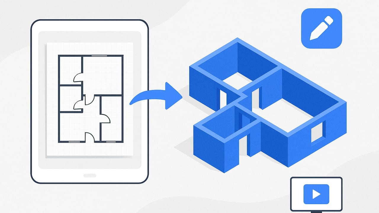
Turning a paper plan into a spatially accurate 3D model isn’t just a neat trick—it’s the fastest way to validate design concepts, visualize furniture placement, and communicate changes with clients or contractors. This guide explains how to create a 3d room layout from 2d blueprint scan sources with professional-level accuracy, using a clean, repeatable workflow that works whether you prefer mobile apps, CAD/BIM, or a hybrid process.
What You’ll Need
- Source imagery: A high-contrast, black-and-white plan (photo or scan). Aim for at least 300 DPI if scanning; when photographing, use good lighting and avoid skew.
- Scale information: A printed scale bar (e.g., 1:100), or at least one known dimension (e.g., “Bedroom: 12'–0””).
- Software options: A mobile app that reads plans into 3D, or CAD/BIM software for tracing and extruding. Image editing software helps with clean-up.
- Time: 15–90 minutes depending on plan complexity and method.
Step-by-Step: From 2D Scan to 3D Room Layout
1) Capture a Clean Plan Image
- Flatten the paper. Remove folds and tape down corners to avoid shadows and curvature.
- Shoot square-on. Keep the camera parallel to the plan; avoid perspective skew. If you must shoot off-axis, plan to dewarp the image.
- Lighting matters. Use even ambient light; avoid glare and heavy shadows.
- Resolution. Scans at 300–600 DPI are ideal. For photos, ensure legible text and crisp linework when zoomed in 200%.
2) Clean the Image for Extraction
- Convert to pure black-and-white. Increase contrast; use thresholding to remove gray smudges and background noise.
- Remove artifacts. Erase fold lines, stamps, or handwritten notes that confuse vectorization/AI.
- Deskew and dewarp. Most image editors have perspective correction; straighten the plan edges so they are perfectly horizontal/vertical.
3) Establish True Scale
Scaling is the backbone of accuracy. You can scale by a known dimension or a printed scale bar.
- Known dimension method: Measure the pixel distance between two endpoints of a labeled dimension, then compute the scale factor.
- Scale bar method: Measure pixels along the scale bar to determine pixels per real-world unit.
Use this quick formula if you measured a labeled dimension directly:
# Simple pixel-to-meters example
pixels_between_ticks = 420   # pixels measured between dimension ticks
labeled_length_m = 3.500     # 3.5 m from the plan
px_to_m = labeled_length_m / pixels_between_ticks

# Convert other measured spans
wall_length_px = 842
wall_length_m = wall_length_px * px_to_m
print(round(wall_length_m, 3))
Pro tip: Validate scale with a second dimension. If both compute within ±1% tolerance, your scale is trustworthy.
4) Interpret the Plan Elements
- Walls: Typically two parallel lines; lineweight indicates load-bearing vs. partitions.
- Openings: Doors, swings, windows symbolized by breaks and arcs; mark widths and sill heights if available.
- Structural columns/beams: Squares/rectangles or hatching; important for ceiling heights and clearances.
- Annotations: Dimension strings, room labels, and level markers guide height and layout.
5) Build the 3D in Your Preferred Tool
Depending on your software, you’ll either trace, vectorize, or let an AI routine detect walls and openings automatically.
- Trace or detect walls: Use wall tools set to correct thickness. Snap to corners; ensure orthogonality unless plan specifies angled walls.
- Insert doors and windows: Match widths and types (swing, pocket, sliding). Set head/sill heights per notes or typical standards.
- Define room heights: Use the plan’s floor-to-ceiling dimension; if not given, assume a standard and note it as a variable.
- Extrude or auto-generate: Convert the traced floor plan into 3D; most tools create walls from linework or wall entities automatically.
6) Add Fixtures, Finishes, and Furniture
- Fixtures: Sinks, toilets, built-ins, wardrobes—place to scale.
- Materials: Apply basic materials (paint, tile, wood). Start with neutral finishes to focus on layout first.
- Furniture: Use scaled assets; validate clearances for circulation and door swings.
7) Review and Export
- Clash and clearance checks: Door swing overlaps, window heights against counters, path widths around furniture.
- Output: Export still renders (e.g., 4K PNG) and, if needed, a walkthrough or orbit animation.
Which Method Should You Use?
There are three common approaches to building a 3d room layout from 2d blueprint scan images. Your choice depends on speed, accuracy needs, and your software comfort.
| Method | How it Works | Speed | Accuracy | Learning Curve | Best For |
|---|---|---|---|---|---|
| Manual CAD/BIM Tracing | Import image, scale, trace walls/doors, extrude | Slow–Moderate | High (if careful) | Moderate–High | Complex plans, pro control |
| Semi-Automated Vectorization | Clean image, auto-detect lines, refine, extrude | Moderate | Medium–High | Moderate | Medium complexity, mixed accuracy needs |
| AI-Driven Mobile/Desktop App | Upload scan, auto-detect walls/openings, auto 3D | Fast | High on clean plans | Low | Quick turnarounds, field workflows |
Accuracy Essentials (Don’t Skip These)
- Scale from multiple references: Confirm using two or more known dimensions.
- Wall thickness: Set typicals (e.g., 90–100 mm internal partitions; 150–300+ mm externals), or read from the plan.
- Door and window sizes: Standard widths vary by region. Use plan labels when available; otherwise, adopt local standards and note assumptions.
- Ceiling height consistency: If the plan indicates bulkheads or dropped ceilings, model them to avoid misleading visuals.
- Dimension reconciliation: If the sum of room dimensions differs from overall dimension by more than 1–2%, recheck scale and wall thickness assignments.
Common Pitfalls and How to Fix Them
- Skewed or warped photos: Use perspective correction before scaling.
- Fuzzy linework: Increase contrast or re-scan. AI detectors struggle with gray, low-contrast ink.
- Ambiguous door swings: If arcs are missing, infer from context (hinge side near wall corner). Flag assumptions in notes.
- Missing heights: Default to regional standards and mark unknowns; avoid hardcoding without documentation.
- Mirrored imports: Some imports flip horizontally—confirm by reading text on the plan. If mirrored, flip before tracing.
A Mini Case Study: Bedroom with Ensuite
Goal: build an accurate 3D room layout from 2D blueprint scan for a 12' × 15' bedroom with a 5' × 8' ensuite and a 6' closet.
- Capture: Shoot the plan straight-on under diffuse light. Deskew corners in an image editor until edges are perfectly vertical and horizontal.
- Clean: Convert to pure black-and-white. Remove a stray revision stamp overlapping the closet door.
- Scale: Measure the pixel distance for the labeled 12' wall; compute px-to-feet. Validate against the 15' dimension—difference is 0.6% (acceptable).
- Trace: Set interior wall thickness to 4.5" (stud plus drywall). Trace the bedroom shell, then the ensuite and closet partitions.
- Openings: Place a 3' hinged door to the bedroom, a 2'6" door to the ensuite, and double 5' sliders for the closet. Confirm swing clearances.
- Heights: Assign 8'–9' ceiling based on notes; add a 7' shower head height and 3' vanity height for realistic visualization.
- 3D generation: Extrude walls, apply basic materials: painted plaster for walls, LVP floor in the bedroom, tile in the ensuite.
- Furnish: Queen bed centered on the long wall with 24" nightstand clearances; 36" walkway maintained to closet doors; 30" clearance in front of vanity and toilet.
- Review: Run a quick clearance audit; nudge the bed 3" to maintain door swing comfort. Adjust lighting to daylight plus a 3000K bedside lamp.
- Export: Produce two 4K stills: one from the doorway showcasing layout, one corner perspective highlighting circulation. Save a 15-second orbit clip for the client.
Quick Math for Scales and Areas
When your scan has a printed scale (e.g., 1:100), you can confirm your results with DPI math:
- Inches across the drawing = pixels ÷ DPI
- Real length = drawing inches × scale factor (e.g., ×100 for 1:100) × 25.4 mm/inch
Sanity check: compute floor area from the 3D model and compare to the plan’s stated area. A mismatch over 2–3% indicates a scaling or wall-thickness issue.
Presentation Tips for Compelling 3D Renders
- Camera height: 1.4–1.6 m for eye-level room views; 2.2–2.4 m for wide interior shots.
- Field of view: 50–70° to avoid distortion while capturing context.
- Lighting: Combine a physical sky or HDRI with a few area lights; avoid overexposure on white walls.
- Material realism: Subtle gloss and bump maps add credibility; keep textures at appropriate scale.
- Export quality: 3000–4000 px on the long edge for print-ready stills; consider denoising for low-render-time workflows.
FAQ
Can I build a 3D model if my plan doesn’t include a scale?
Yes. Use any known measurement (door width, bed, standard bathtub length) to set an initial scale, but verify with a second known dimension to minimize error.
How accurate can a 3d room layout from 2d blueprint scan be?
With a clean image, proper scaling, and careful interpretation, ±1% linear accuracy is achievable. Image skew, poor resolution, and ambiguous symbols are the main accuracy risks.
Do I need CAD experience?
No. AI-driven tools can automate wall and opening detection. For complex geometry, basic CAD skills still help refine results.
What if the plan shows dimensions in feet and inches?
Work in imperial units within your software or convert to millimeters. Be consistent and document assumptions.
How do I handle non-orthogonal or curved walls?
Trace using polyline or spline tools. Ensure snapping is off when following curves; check radius values if noted on the plan.
A Practical Checklist
- Photo or scan is deskewed and high contrast
- Scale verified with at least two dimensions
- Wall thickness set per plan or local standards
- Doors/windows sized and placed; swings cleared
- Ceiling height assigned; bulkheads modeled
- Fixtures and furniture placed to scale
- Clearances verified; notes added for assumptions
- Renders exported at presentation quality
Building an accurate 3d room layout from 2d blueprint scan data is ultimately about disciplined setup: clean imagery, verified scale, and careful interpretation. Whether you prefer manual tracing for maximum control or an AI-assisted workflow for speed, the principles above will keep your results precise, presentable, and easy to revise.
If you want a fast, mobile-first path from phone photo to high-fidelity 3D, the iOS app Floor Plan to 3D can ingest black-and-white scans and auto-generate dimensional 3D layouts while preserving proportions, with export options for presentation-ready images.
