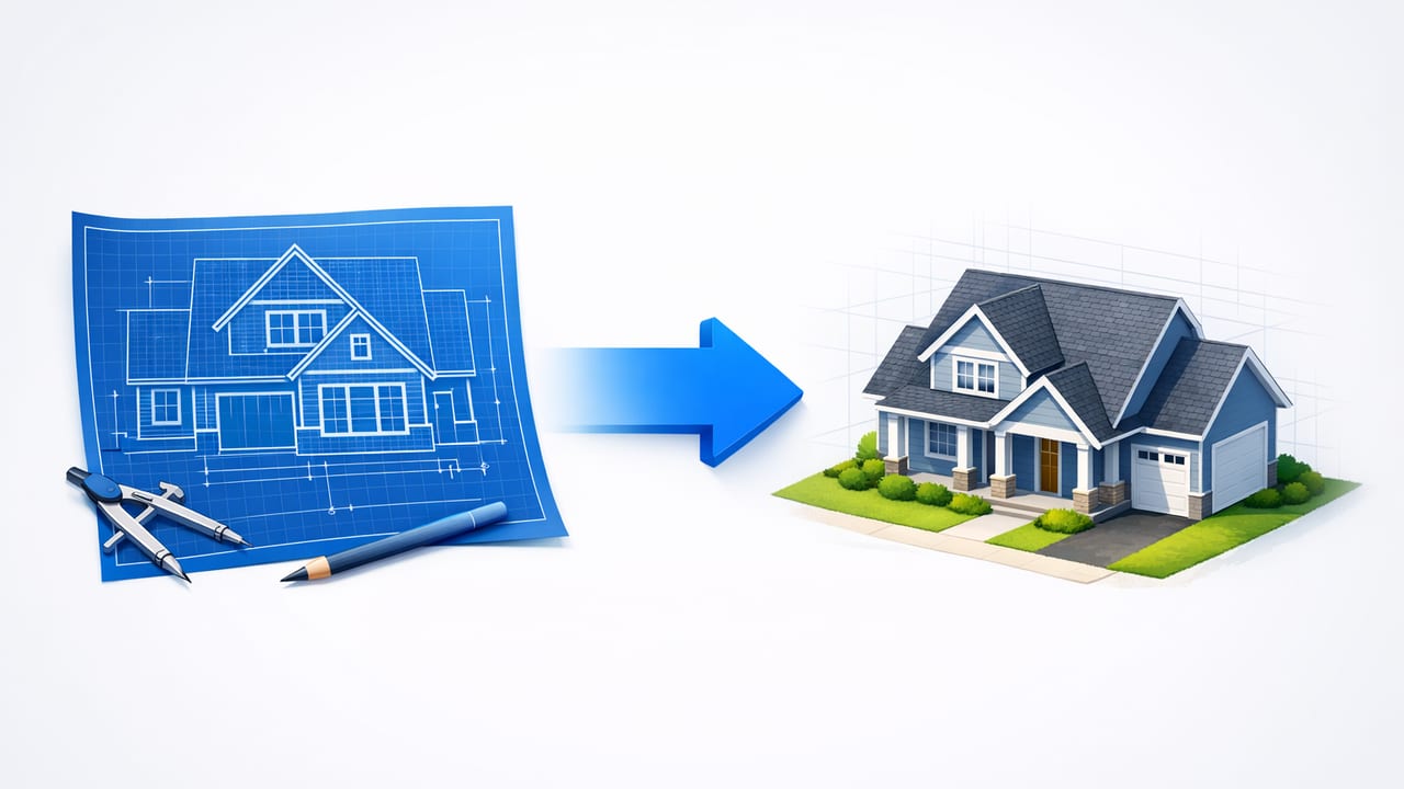
When you convert blueprint to 3d, you’re doing more than making something “look nice.” You’re translating construction intent—walls, openings, dimensions, circulation—into a visual model that helps people make decisions. Done well, 3D conversion reduces misunderstanding, speeds up approvals, and surfaces design problems early (before they become change orders).
This guide breaks down a reliable workflow for turning black-and-white blueprints into clear 3D renders, with a focus on accuracy first: how to prep your plan, preserve scale, interpret symbols, handle missing information, and produce renovation-ready images that communicate.
Why 3D from blueprints changes decision-making
Blueprints are efficient for builders but challenging for many homeowners, investors, and non-technical stakeholders. A 3D view makes it easier to evaluate:
- Flow: whether circulation makes sense (pinch points, awkward turns, blocked doors).
- Proportions: room size perception vs. raw dimensions.
- Furniture fit: realistic placement and clearances.
- Renovation scope: what changes are structural vs. finish-level.
- Exterior impact: window/door changes, massing, and curb appeal concepts.
Step 1: Start with the cleanest source possible
The biggest quality jump usually comes from input quality. Before you convert blueprint to 3d, choose the best available source:
- Vector PDF (best): crisp lines, consistent scale, fewer artifacts.
- High-resolution scan: aim for 300–600 DPI if scanned.
- Phone photo (last resort): workable if evenly lit and squared to the page.
Quick capture checklist (scans/photos)
- Ensure the page is flat (no curl near edges).
- Use even lighting; avoid shadows from your hands/phone.
- Keep the camera parallel to the blueprint to avoid perspective distortion.
- Include the scale note and at least one dimension string in view.
Step 2: Decide what “accurate” means for your project
Not every blueprint-to-3D conversion needs the same fidelity. Define your target accuracy early so you don’t over-model details that won’t matter.
| Use case | What must be accurate | What can be approximate |
|---|---|---|
| Early renovation feasibility | Wall locations, room sizes, door swings, window placement | Finishes, cabinetry internals, lighting layout |
| Real estate marketing visuals | Overall proportions, key openings, furniture scale | Exact trim profiles, minor dimension strings |
| Contractor coordination | Dimensions, ceiling heights, structural walls, clearances | Decor, staging items, paint color exploration |
| Interior layout planning | Furniture footprints, circulation clearances | Material specs, appliance model numbers |
Step 3: Anchor the scale (the make-or-break step)
Most errors in 3D conversion come from a bad scale anchor. Even if the blueprint shows “1/4" = 1'-0"”, scans and photos often shrink/expand slightly. Instead, anchor the model using a known dimension on the plan.
How to set a reliable scale anchor
- Pick a dimension that’s long and unambiguous (e.g., overall building width or a major room length).
- Measure the same segment digitally (or within your conversion tool).
- Apply a scale correction so that segment matches the printed dimension.
- Verify by checking 2–3 other dimensions in different areas of the plan.
Rule of thumb: If two dimensions don’t agree after scaling, the input is distorted (photo perspective) or the plan itself has inconsistencies. Fix the source first or accept a defined tolerance.
Step 4: Interpret blueprint symbols correctly (so your 3D is believable)
When you convert blueprint to 3d, the translation of symbols into 3D objects is where “accurate” becomes “useful.” Focus on the symbols that affect layout and sightlines:
- Walls: distinguish exterior vs. interior thickness where possible.
- Doors: confirm swing direction; check for clashes with nearby fixtures.
- Windows: note size tags (e.g., 3040) and sill height if available.
- Stairs: confirm rise/run direction and headroom zones.
- Plumbing fixtures: helps validate bathroom/kitchen planning and clearances.
Common symbol pitfalls
- Pocket doors are often missed and modeled as swing doors, breaking furniture layouts.
- Exterior wall offsets (insulation layers, cladding) can shift window depth in 3D.
- Columns or beams may be drawn subtly and get omitted—then your open plan looks unrealistically clean.
Step 5: Add the missing third dimension (heights) strategically
Many floor plans don’t include ceiling heights, soffits, or window head heights. You can still produce strong 3D renders if you use a consistent approach:
- Set a default ceiling height (e.g., based on region or the plan notes) and document it.
- Mark exceptions (vaults, dropped ceilings, tray ceilings) if elevations or sections exist.
- Use doors as reference: a typical interior door height can help sanity-check the scene scale.
If you’re presenting to stakeholders, it’s better to be explicit than accidentally misleading:
“Ceiling height modeled at 8'-0" where not specified.”
Step 6: Validate with a clearance-based review (layout reality check)
A 3D model becomes decision-ready when it passes basic clearance rules. After converting, run a quick “walkthrough” check:
- Door clearance: ensure doors open without hitting toilets, vanities, or furniture.
- Hall widths: verify pinch points at corners and near door jambs.
- Kitchen work zones: confirm aisle widths and appliance door swings.
- Bedroom basics: verify bed placement with side clearances and closet access.
Mini-checklist: furniture footprints
Even rough staging dramatically improves comprehension. Keep it simple and consistent:
- Sofa: 84–96 in wide
- Queen bed: 60 x 80 in
- Dining chair pull-back clearance: ~24 in behind chairs
- Comfortable walkway: ~36 in (more in key paths)
Step 7: Create two render sets: “truth” and “ideas”
The most effective blueprint-to-3D deliverables separate what’s documented from what’s conceptual:
- As-is (truth) set: faithful to the blueprint, minimal styling, labels preserved where useful.
- Redesign (ideas) set: finish options, furniture, lighting mood, exterior refresh concepts.
This avoids a common communication failure: a stakeholder approves a concept render assuming it reflects existing conditions exactly.
Step 8: Preserve labels and room intent for faster collaboration
Room names and dimensions aren’t just annotations—they’re collaboration metadata. If your 3D workflow supports it, keep or re-add:
- Room labels (Kitchen, Bedroom 2, Mechanical)
- Key dimensions (overall, critical spans, bathroom/kitchen constraints)
- Notes (e.g., “existing,” “new,” “remove”)
For teams juggling multiple revisions, a consistent naming convention also helps prevent version confusion. Here’s a simple pattern you can copy:
ProjectName_Level_Discipline_Status_v##
MapleSt_L1_Arch_AsIs_v03
MapleSt_L1_Arch_RedesignA_v02
MapleSt_Exterior_Concept_CurbAppeal_v01
Step 9: Handle imperfect blueprints without stalling
Real plans are messy: old scans, missing dimensions, hand-marked changes. You can still convert blueprint to 3d effectively by using “assumptions with flags.”
A practical assumptions log
- Assumption: Wall thickness set to 4.5 in for interior partitions where unspecified.
- Assumption: Window head height aligned at 6'-8" unless noted.
- Open question: Is the pantry door a pocket door or swing?
This keeps the project moving while making it easy to confirm details later.
Step 10: Export for the audience (not the modeler)
The best render is the one that gets approved quickly and correctly. Choose outputs based on who needs to decide:
- Homeowners: perspective views, simple material palettes, staged rooms.
- Contractors: orthographic 3D views, dimension callouts, clear “as-is vs. proposed.”
- Real estate: bright, clean renders with realistic furniture scale and minimal clutter.
Export checklist
- Include at least one top-down 3D view for layout comprehension.
- Provide 2–4 key interior perspectives (kitchen, living, primary bath/bed).
- For exteriors, show front elevation perspective plus one angled view.
- Use consistent camera heights so “before vs. after” comparisons are fair.
Frequently asked questions
Can I convert blueprint to 3d if I only have a photo?
Yes, but correct for perspective distortion first (square the image) and anchor scale using a known dimension. Expect more manual cleanup than with a vector PDF.
How accurate can blueprint-to-3D be?
If the blueprint is dimensioned and your scale anchor is correct, you can achieve layout-level accuracy suitable for planning and presentations. Construction-ready accuracy typically requires cross-checking against site measurements and elevations/sections.
What’s the fastest way to improve realism without losing time?
Add basic furniture footprints, set consistent ceiling heights, and use simple material blocks (wood, tile, paint). Realism improves more from correct proportions and lighting than from intricate decor.
Putting it all together: a repeatable workflow
To summarize, a reliable blueprint-to-3D pipeline looks like this:
- Start with the cleanest plan source available.
- Define your target accuracy based on the use case.
- Anchor scale using a known dimension and verify across the plan.
- Translate critical symbols (walls, doors, windows, stairs) correctly.
- Add heights with documented assumptions.
- Run a clearance-based layout review.
- Produce an as-is set and a redesign set.
- Export visuals tailored to the decision-maker.
If you want to experiment with this workflow on iOS—especially for quick 3D conversion plus AI-guided room planning—an app like Floor Plan to 3D & Home Redesign can help you move from blueprint to presentable 3D renders without heavyweight modeling software.
