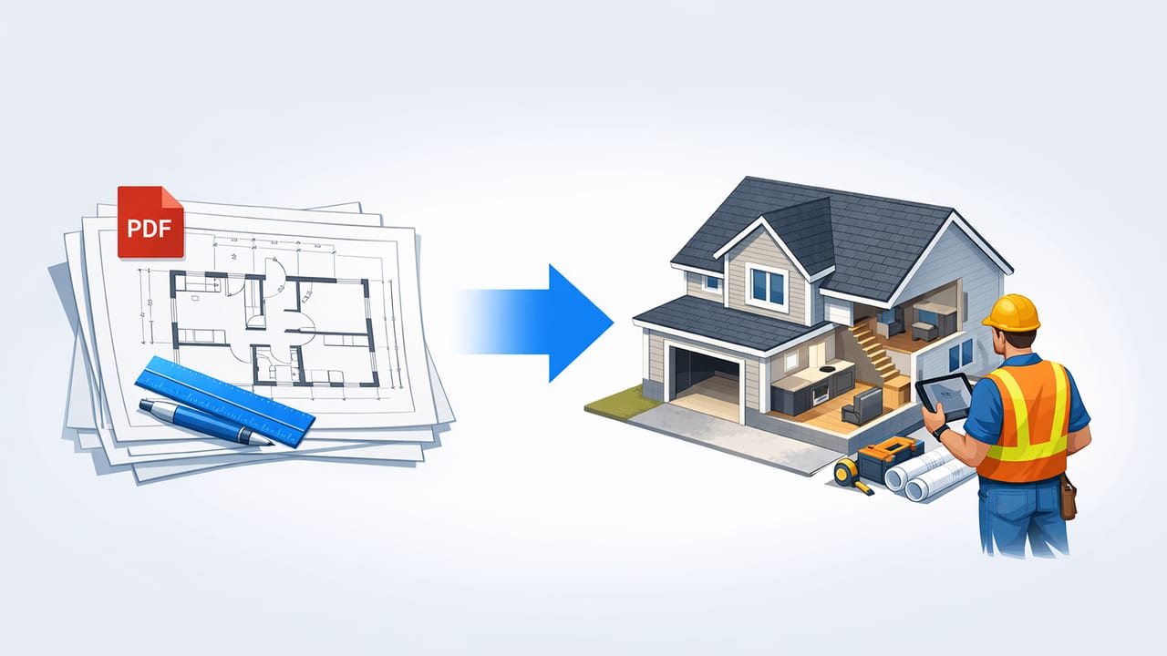
PDF plan sets are everywhere: emailed by architects, downloaded from plan rooms, or shared via project portals. They’re fast to distribute, easy to mark up, and consistent across devices. But for field coordination, client approvals, and preconstruction planning, a contractor friendly 3d model from pdf plans can reduce ambiguity and speed up decisions—without turning your team into full-time BIM modelers.
This guide breaks down a realistic workflow that contractors, estimators, and project managers can use to convert PDF plans into a clean, buildable 3D representation. You’ll learn what “contractor-friendly” really means, how to set up your inputs, what to model (and what not to), and how to quality-check and export the result for subs and stakeholders.
What “contractor-friendly” means (and what it doesn’t)
Contractor-friendly 3D is not necessarily a fully detailed BIM with every assembly, fastener, and manufacturer-specific family. Instead, it’s a model that is:
- Dimensionally reliable for key layout decisions (rooms, openings, clearances).
- Simple enough to build quickly from PDFs and revise when addenda arrive.
- Readable for non-modelers (supers, owners, subs).
- Exportable to standard formats (images, PDF sheets, IFC/OBJ/FBX where appropriate).
- Aligned to field needs: sequencing, clash awareness, and scope communication.
Think of it as construction visualization with discipline: accurate geometry at the level that supports real decisions, without unnecessary detail that burns schedule.
Before you start: confirm the goal and the level of detail
PDF-to-3D work fails most often due to unclear expectations. Start with two quick definitions.
1) Define your use case
- Client buy-in: layout, massing, finishes, sightlines.
- Trade coordination: ceilings, soffits, major MEP routes (conceptual).
- Estimating support: areas, counts, basic takeoff checks.
- Logistics: equipment clearances, access paths, staging.
2) Pick an LOD target (simple scale)
You can use a lightweight LOD scale to keep scope in check:
- LOD-S (Sketch): walls/rooms/openings only; fast approval visuals.
- LOD-C (Construction): adds ceilings, stairs, key casework, structural thicknesses.
- LOD-K (Coordination): adds major MEP zones and clash-sensitive volumes (not full fabrication).
For many small-to-mid projects, LOD-C is the sweet spot for a contractor friendly 3d model from pdf plans.
Step-by-step workflow: PDF plans to a reliable 3D model
Step 1: Inspect and “clean” the PDF set
Not all PDFs are equal. Identify what you have:
- Vector PDF (true CAD lines): crisp zoom, selectable linework, often easier to trace.
- Raster PDF (scanned images): may be skewed, low DPI, harder to scale accurately.
Do a quick cleanup pass:
- Confirm you have the latest revision and addenda.
- Find at least one dimensioned reference per floor (grid spacing, overall length, or a long dimension string).
- Extract the sheets you need: plans, reflected ceiling plans, door/window schedules, and sections for heights.
Step 2: Establish scale and orientation (the non-negotiable step)
Every downstream error usually traces back to scale. Calibrate the model using a long, unambiguous dimension (e.g., gridline A–F spacing or an overall building dimension). Avoid scaling from short dimensions like door widths unless you have no alternative.
Best practice checklist:
- Use one primary reference for scaling and two secondary checks (e.g., another overall dimension).
- Lock the PDF underlay so it can’t drift.
- Set project north (or at least a consistent orientation) so exports remain comparable across revisions.
Step 3: Trace the building envelope and major partitions
Start with what drives layout decisions:
- Exterior walls and core (shafts, stairs, elevators).
- Fire-rated corridors and egress paths.
- Major room boundaries (units, suites, key program areas).
Tip: If the PDF shows wall types, model typical thicknesses. If not, use conservative defaults and note assumptions (e.g., 6 in interior, 8 in exterior) until confirmed by sections or details.
Step 4: Add openings using schedules (don’t eyeball)
Doors and windows are where “pretty” models fail construction use. Rely on schedules and tags:
- Place openings by tag location from the plan.
- Assign widths/heights from the schedule.
- Validate swing direction for doors that affect clearance and accessibility.
If you can’t access schedules, at least model openings as generic placeholders with a clearly labeled assumption set.
Step 5: Set vertical constraints (heights from sections)
PDF floor plans rarely tell the whole story vertically. Use building sections, enlarged details, and RCPs to establish:
- Floor-to-floor heights and ceiling heights.
- Soffits, bulkheads, and drops that affect MEP.
- Stair geometry and landings (critical for egress and headroom).
Modeling ceilings as simple planes is often enough to support trade conversations and client visuals.
Step 6: Add “coordination volumes” instead of detailed MEP
For contractor-friendly coordination, you can often represent major systems as keep-out zones or simplified volumes:
- Main duct trunks as rectangular prisms with clearance buffers.
- Plumbing stacks as cylinders/boxes.
- Electrical rooms and panel clearances as bounding boxes.
This reduces clashes early without the overhead of building fabrication-level systems from PDFs.
Step 7: Document assumptions inside the model
Make your model self-explanatory for anyone who opens it later. Add notes like:
- “Wall thickness assumed 6 in typ unless noted.”
- “Ceiling height set to 9'-0" typ from A-301.”
- “Window heights per schedule W1–W7; sill heights not shown—assumed 3'-0".”
Quality control: the 10-minute verification routine
Before sharing, run a quick QC pass. The goal is to catch the common errors that undermine trust.
- Scale check: measure two long spans and one short span against the PDF dimensions.
- Room adjacency: ensure major spaces connect correctly (no accidental gaps or overlaps).
- Opening alignment: doors centered on walls, windows not floating, no duplicate openings.
- Stair/egress sanity: stair runs align to plans and sections; landings exist.
- Height check: ceilings and floor levels consistent across the model.
- Clash scan (visual): look for obvious conflicts at soffits, shafts, corridors.
- Export test: generate one image/PDF view to confirm lineweights, cropping, and readability.
A model doesn’t have to be perfect to be useful, but it does have to be consistent, scaled, and honest about assumptions.
Recommended deliverables contractors actually use
The best “deliverable” depends on who needs it. Consider packaging the model outputs like this:
| Audience | Most useful output | Why it works |
|---|---|---|
| Owner / Client | High-res rendered images + short walkthrough | Speeds approvals and reduces change orders |
| Field (Super / Foreman) | Annotated views (plan + 3D) in PDF | Easy to print, mark up, and reference on site |
| Subcontractors | Simplified 3D model + key dimensions | Supports coordination without drowning them in detail |
| Estimating / Precon | Area schedules + basic quantities | Cross-checks takeoffs from the 2D set |
Naming and versioning: a small habit that prevents big confusion
When revisions arrive, the model can drift unless you’re strict about versioning. Here’s a simple convention you can adopt.
PROJECTCODE_Level-Scope_Rev_YYYYMMDD

Example:
RIVERTOWN_L2-ArchShell_R03_20260318
RIVERTOWN_L2-CoordZones_R03_20260318
Also store a one-page changelog (even a text note) listing what changed between revisions: “Moved corridor wall at Grid C; raised ceiling in Lobby; updated Door D12 width.”
Common pitfalls (and how to avoid them)
Relying on a single sheet
Plans can conflict with sections, RCPs, or enlarged details. Cross-reference heights and critical assemblies.
Over-modeling early
Detailed casework, trims, and fixtures can wait. Nail layout and openings first; keep detail proportional to the decision you’re supporting.
Ignoring printable communication
Many stakeholders still prefer PDFs in the field. Provide a few annotated views that match sheet logic: plan, two interiors, one overall axonometric.
Not stating assumptions
Unstated assumptions get mistaken for facts. If a dimension or height is guessed, label it.
Mini FAQ: contractor friendly 3d model from pdf plans
Can you create a reliable 3D model from scanned PDFs?
Yes, but expect extra time for skew correction and scaling checks. Always validate against at least two long reference dimensions.
Do you need BIM software to do this?
Not always. Many workflows use a simpler 3D tool for layout visualization, especially for LOD-S or LOD-C. BIM platforms help when you need schedules, parametric assemblies, or coordination exports.
How accurate should the model be?
Accurate enough to support the intended decision. For layout approvals, consistent room sizes and openings matter most. For coordination, heights and clearances become critical.
What’s the fastest path to a presentable result?
Start with one floor, model envelope + partitions + openings, set heights from a section, and export 3–6 key views. Expand after stakeholders confirm the direction.
Closing thoughts
A contractor friendly 3d model from pdf plans is less about flashy rendering and more about clarity: consistent scale, readable geometry, and documented assumptions. When done well, it becomes a shared reference that reduces RFIs, tightens coordination, and speeds approvals—without requiring a full BIM build.
If your workflow starts on an iPhone or iPad and you want a quick way to turn black-and-white plans into a usable 3D baseline, Floor Plan to 3D is one option teams use to generate clean visuals and export high-resolution renders for presentations.
