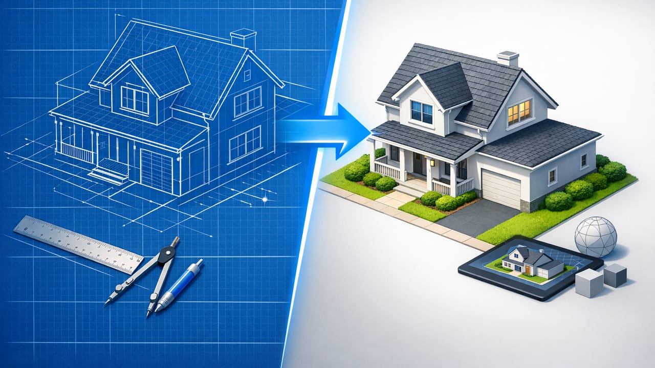
Converting a blueprint to 3d is no longer just a visualization upgrade. Done well, it becomes a decision-making tool for renovation previews, room planning, material takeoffs, and clearer stakeholder communication. Done poorly, it becomes a glossy but misleading model that causes layout mistakes, ordering errors, and rework.
This guide focuses on what matters most: accuracy. You will learn how to prepare a blueprint for conversion, how to validate scale and proportions in the 3D result, and how to use that model for practical redesign decisions without getting trapped in heavyweight software.
Why accuracy is the real goal (not just a nice render)
A clean 3D render is helpful, but an accurate 3D model is valuable. The difference is whether you can trust the output to answer questions like:
- Will a 36-inch fridge door clear the island?
- Does that new shower layout still meet minimum clearances?
- Will a sectional block the main circulation path?
- Do the window sizes and placements match the plan?
When converting a blueprint to 3D, think of accuracy as three layers:
- Scale: the model is correctly sized (overall and per room).
- Geometry: walls, openings, and corners align and close cleanly.
- Semantic fidelity: labels, dimensions, and room intent are preserved so the model stays interpretable.
What types of blueprints convert best
Blueprint-to-3D tools and AI room planners can work with many inputs, but results improve dramatically when the source is clean. Here is a quick quality breakdown:
| Source type | Typical accuracy | Main risk | Best practice |
|---|---|---|---|
| Original PDF plan (vector or high-res) | High | Hidden scale differences between sheets | Confirm a known dimension (e.g., door width) |
| Clean scan of printed blueprint | Medium to high | Skew, shadow, fold distortion | Scan flat, crop, and correct perspective |
| Phone photo of plan on a table | Medium | Perspective warp and blur | Shoot straight-on, good lighting, high resolution |
| Hand-drawn plan | Low to medium | Ambiguous dimensions and wall thickness | Add at least one explicit reference dimension |
Step 1: Prep the blueprint so the 3D conversion stays dimension-true
Most conversion errors originate in the input image. Before you run any blueprint-to-3D workflow, do this quick prep.
1) Crop to the plan area (remove distractions)
Cut out title blocks, notes, legend pages, and unrelated elevations if you are converting a single floor. Extra text and symbols can confuse recognition and create phantom walls.
2) Correct perspective and skew
If your blueprint is photographed, make sure lines that should be parallel are parallel in the image. Even a small keystone distortion can throw off scale when the tool tries to infer geometry.
3) Ensure readable dimensions and labels
Labels help tools assign room types and preserve layout intent. If dimensions are unreadable, you may still get a pretty 3D render, but you lose the ability to verify accuracy.
4) Identify one or two reference dimensions you trust
You need a known measurement to validate the output. Good references:
- Standard door width (often 30–36 inches depending on location)
- Overall exterior width of the building
- A labeled room dimension like “12'-6"”
Step 2: Convert blueprint to 3D with an “anchor-first” approach
The fastest way to keep a 3D model honest is to anchor the scale early and then build confidence outward.
- Anchor a known dimension (for example, verify one wall length or a door width).
- Check adjacent rooms (do the next two or three measurements match the plan?).
- Validate the perimeter (overall footprint and exterior corners).
- Only then proceed to furnishings, finishes, and redesign options.
A simple scaling sanity check (when you have pixels)
If your workflow provides a pixel measurement (or you can measure it in an image editor), you can approximate scale:
// Convert a pixel distance to real-world distance using a known reference
// known_real = the real length of a reference wall (in inches, cm, etc.)
// known_px   = the pixel length of that same wall in the image
// target_px  = pixel length of another wall you want to estimate

scale = known_real / known_px
estimated_real = target_px * scale
This is not a replacement for dimension labels, but it helps detect obvious drift early (for example, a room that becomes 15% larger than the blueprint).
Step 3: Run an accuracy checklist on the 3D result
After conversion, do not jump straight to finishes and decor. Spend five minutes validating the 3D output against the blueprint. Here is an accuracy-first checklist you can reuse.
Geometry checks (layout integrity)
- Walls close cleanly: no gaps, overlaps, or double lines at corners.
- Wall thickness is consistent: especially between interior partitions and exterior walls.
- Door swings and openings are placed on the correct wall and in the correct orientation.
- Stairs: count risers/landing presence, and confirm direction.
Scale checks (dimension integrity)
- Verify overall footprint (width and depth) using labeled dimensions.
- Verify one small element (door width) and one large element (long exterior wall).
- Check room-to-room proportion: kitchens and baths often reveal scaling errors quickly.
Semantic checks (meaning integrity)
- Room labels match the plan (BED, BATH, KITCHEN, etc.).
- Dimensions are preserved where possible (or at least not contradicted).
- Openings (windows/doors) align with the plan notes if present.
Trust the 3D render only after the model passes basic measurement checks. A photoreal look can hide structural inaccuracies.
Using the 3D model for redesign without breaking the plan
Once your blueprint-to-3D model is stable, you can start exploring redesign options safely. The key is to separate layout changes from surface changes.
Low-risk changes (great for fast renovation previews)
- Paint, flooring, and finish updates
- Cabinet style swaps (keeping footprint)
- Lighting and fixtures
- Empty-room staging (furniture layouts)
These are ideal for AI-guided room planning because the underlying geometry stays intact.
Medium-risk changes (validate with measurements)
- Moving non-structural partitions
- Resizing door openings
- Kitchen reconfiguration that changes appliance spacing
When you test these, re-run the scale checks: clearances, circulation paths, and door conflicts.
High-risk changes (use 3D for concept, then confirm professionally)
- Removing walls (possible structural impact)
- Relocating plumbing stacks
- Changing window sizes on exterior walls
A 3D model is excellent for concept validation and communication, but structural and code decisions should be confirmed with qualified professionals.
Exterior refresh: what blueprint-to-3D can (and cannot) tell you
For exterior refresh work, 3D is most useful when you combine footprint accuracy with clear assumptions. A floor plan-derived model can support:
- Massing and proportion previews (how additions or rooflines might read)
- Window rhythm checks (spacing and alignment)
- Material palette exploration (siding, trim contrast, stone accents)
However, if the blueprint does not include elevations, roof pitch, or facade details, treat exterior results as conceptual. Use the model to iterate faster, then refine with elevation references.
Common pitfalls (and how to avoid them)
Pitfall 1: Assuming all plans are drawn to the same scale
Blueprint sets often include different scales for different sheets. Always anchor your 3D conversion to a dimension on the same sheet you are converting.
Pitfall 2: Ignoring wall thickness and door/window conventions
Some plans use simplified linework. If openings are stylized, confirm their meaning before trusting the 3D placement.
Pitfall 3: Letting furniture “prove” the layout
Auto-furnished rooms can look plausible even when the room is the wrong size. Measurements, not furniture fit, should be your primary validation.
Pitfall 4: Skipping the export step until the end
If you plan to use the 3D output in proposals or presentations, test exports early (image resolution, clean perspectives, and consistent labeling). This avoids last-minute rework when you discover the output is too small or cluttered.
A practical mini-workflow you can repeat
- Capture: high-res PDF or a flat, straight-on scan/photo.
- Clean: crop to one floor; remove distractions.
- Convert: generate the 3D layout.
- Anchor: validate one known dimension.
- Verify: check 3–5 more measurements across the plan.
- Iterate: test redesign options (starting with low-risk changes).
- Export: produce high-resolution images for sharing.
FAQ: blueprint to 3D conversions
How accurate can a blueprint-to-3D conversion be?
With a clean source blueprint and readable dimensions, accuracy can be very strong for layout and proportional decisions. The biggest accuracy swings usually come from skewed photos, low-resolution scans, or missing reference dimensions.
Do I need CAD to do this well?
No. Many workflows produce reliable 3D renders and room planning previews without CAD. The key is using an accuracy checklist and validating scale before making design decisions.
What is the fastest way to catch a bad conversion?
Check one small reference (door width) and one large reference (overall exterior wall). If either is off, the rest of the model is likely drifting too.
Final tip: treat 3D as a measurement-backed conversation
The best blueprint-to-3D outcomes happen when you use 3D for what it does best: rapid iteration, clear communication, and decision support. Pair it with measurement validation, and your 3D render becomes a dependable renovation preview tool rather than just a pretty image.
If you want to try this workflow on iOS, an app like Floor Plan to 3D & Home Redesign can help convert black-and-white plans into clean 3D renders and support quick room planning iterations.
