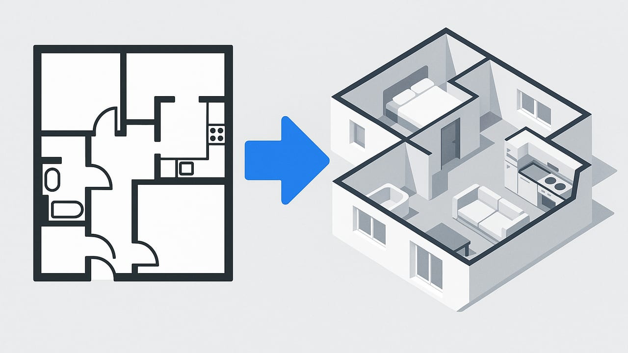
Turning a black and white floor plan to 3D is one of the fastest ways to move from concept to a spatially true visualization. Whether you are a student validating a studio layout, a realtor preparing a listing, or a contractor coordinating trades, the ability to translate monochrome lines into a navigable model can save time, reduce miscommunication, and produce persuasive visuals.
This guide covers the primary conversion methods, image preprocessing, a step-by-step build workflow, accuracy techniques, and export best practices. The goal is to get you from a static 2D plan to a dimensionally reliable 3D model with as few surprises as possible.
What "black and white" implies in floor plans
Monochrome plans rely on line weights, hatches, and symbols instead of color. Understanding these conventions is the foundation of any successful conversion:
- Line weights often distinguish structural walls (thicker) from partitions (thinner).
- Hatches can mark materials (e.g., concrete, insulation) or areas (e.g., wet rooms).
- Symbols represent doors, windows, fixtures, and direction of swing or opening.
- Scale is specified via a ratio (e.g., 1:100) or a scale bar; sometimes only a single known dimension is given.
- Annotations include dimensions, levels, and notes. They are crucial for calibrating the 3D model.
Three primary paths from black and white floor plan to 3D
All workflows boil down to reading geometry and semantics, then building 3D elements at the correct scale. Choose the path that matches your timeframe, accuracy needs, and tool familiarity.
| Method | Typical time | Accuracy potential | Learning curve | Best for |
|---|---|---|---|---|
| CAD/BIM tracing (e.g., FreeCAD, SketchUp, Revit) | 1–6 hours per unit | High (within 1–2% if calibrated) | Moderate to steep | Designers, students, contractors needing edits |
| DCC trace + extrude (e.g., Blender) | 1–4 hours | Medium-high (depends on discipline) | Moderate | Visualizers needing materials/lighting control |
| AI-assisted conversion apps | 5–30 minutes | Medium-high (varies by input quality) | Low | Realtors, rapid proposals, mobile workflows |
Preprocess the plan image for clean, traceable input
Garbage in, garbage out. Spend a few minutes preparing your black-and-white plan so edges are crisp and geometry is easy to interpret.
- Scan or photograph at high resolution: Aim for 300–600 DPI when scanning. When photographing, fill the frame, avoid glare, and shoot square-on.
- Deskew and crop: Correct perspective distortion and align the drawing. Crop away title blocks if they block tracing.
- Increase contrast and binarize: Ensure lines are solid black and backgrounds are clean white; remove shadows and stains.
- Reduce noise: Filter speckles so automatic detectors or your snapping tools don't misread debris as walls.
- Optional vectorization: Convert to SVG using potrace if your tool supports importing vector lines for snapping.
Example commands for common tasks:
# Deskew and binarize with ImageMagick
convert plan.jpg -deskew 40% -threshold 60% -resize 4000x plan_clean.png

# Vectorize to SVG using potrace (via PBM)
convert plan_clean.png -threshold 60% plan.pbm
potrace -s plan.pbm -o plan.svg
Step-by-step: from clean plan to a dimensionally true 3D model
- Import and scale
- Bring the cleaned image (or SVG) into your modeling tool.
- Identify a known dimension (e.g., a labeled room width) or a printed scale bar.
- Use the scale tool to match the image to real units (mm or inches). Lock aspect ratio to avoid distortion.
- Establish layers and guides
- Create layers for walls, openings, annotations, fixtures, and reference lines.
- Set a grid and snapping to endpoints, midpoints, and intersections.
- Define wall thickness and heights
- Read the legend or measure from the plan; common interior partitions are 90–120 mm (3.5–4.75 in), exteriors 150–300 mm (6–12 in).
- Set typical story heights (e.g., 2.6–2.8 m or 8'6"–9'2").
- Trace primary walls
- Trace centerlines or wall faces consistently. If centerlines, offset half the thickness to each side before extruding.
- Resolve non-orthogonal walls with precise angle input (avoid eyeballing).
- Add openings (doors and windows)
- Mark door widths (e.g., 760–910 mm / 30–36 in) and swing directions; cut openings at correct sill and head heights.
- Place window types per symbols; assign sill heights (e.g., 750 mm / 30 in) and heads below lintels.
- Model floors, slabs, and ceilings
- Trace room perimeters to generate floors; add thickness if doing section details.
- Add ceilings at finish height; consider bulkheads if shown.
- Stairs and levels
- Use labeled rises and goings; check total rise equals story height.
- Place landings and handrails per symbol conventions.
- Furnish for context
- Insert scaled furniture to validate circulation and clearances (e.g., 900 mm / 36 in walkways).
- Kitchen and bath fixtures provide instant reality checks on proportions.
- Materials and lighting
- Assign basic materials for legibility: walls (matte off-white), floors (wood/tile), glazing (glass).
- Use daylight plus a few area lights for neutral, informative renders.
- Quality checks
- Measure wall-to-wall widths and confirm against annotations.
- Check gross area deviation; aim for within 1–2% of the plan.
- Verify door swings, window placements, and stair counts.
Common pitfalls and how to avoid them
- Inconsistent wall thickness: If the plan uses different wall types, label them and apply correct thicknesses before extruding.
- Scaling from a photocopy: Some prints are stretched. Always scale from two known dimensions in perpendicular directions to catch distortion.
- Misreading hatches and symbols: Keep a legend handy; hatch patterns often denote material or structural elements.
- Rounded measurements: Rounding multiple times compounds error. Use exact numbers where given.
- Ignoring tolerance: Set an acceptable error band (e.g., ±10 mm / ±3/8 in) and flag larger discrepancies for review.
- Curved walls as polylines: Don’t approximate arcs with too few segments. Use true arcs/splines for accuracy.
Accuracy techniques that pay off
- Reference dimensions: Create non-printing dimensions that mirror key plan annotations; lock them to catch drift.
- Constraints: Use constraints where available (parallel, perpendicular, equal) to enforce intent.
- Snapping discipline: Disable snaps you don’t need; too many snaps cause mis-selections on noisy drawings.
- Orthographic check: Toggle an orthographic camera and compare overlays of the rendered plan to the original for alignment.
- Area cross-check: Compute total area of spaces; compare to plan schedules to verify within tolerance.
Worked example: small apartment plan
Suppose you have a black-and-white plan for a 2-bedroom apartment. The printed note says overall 8.0 m by 10.0 m, typical wall thickness 120 mm, ceiling height 2.6 m, doors 900 mm, windows vary.
- Scale: Import the image, draw a temporary 8,000 mm line over the labeled 8 m side, scale the image so both match.
- Walls: Trace centerlines; offset 60 mm to each side to create wall faces. Extrude walls to 2,600 mm.
- Openings: Place 900 mm doors with 100 mm jambs; cut window openings at 900 mm sill height and 2,100 mm head height.
- Floors/Ceilings: Trace the unit boundary to create a floor slab; add a finish layer if you want section realism. Add a flat ceiling at 2,600 mm.
- Furnish: Drop in a 2,100 x 1,600 mm bed, a 1,800 x 800 mm sofa, 600 mm-deep kitchen counters; confirm 900 mm clear paths.
- Checks: Use the dimension tool to verify each room’s width and length. Confirm total area near 80 m²; reconcile any >2% discrepancy.
Optional pseudo-JSON to capture key parameters you might keep alongside your model:
[
  {'start':[0,0], 'end':[8000,0], 'thickness':120, 'height':2600},
  {'start':[8000,0], 'end':[8000,10000], 'thickness':200, 'height':2600},
  {'door_center':[2000,0], 'width':900, 'swing':'in'},
  {'window_center':[4000,10000], 'width':1500, 'sill':900, 'head':2100}
]
Deliverables and exports that communicate clearly
- Iso/axonometric views: Show wall heights, openings, and furniture in one glance.
- Plan overlays: Render a top-down view and overlay it at 50% opacity on the original to confirm match.
- Sections: Cut through kitchen/bath to reveal clearances and exhaust paths.
- Walkthroughs: Short camera paths help non-technical stakeholders understand scale.
- High-resolution stills: 3000–4000 px on the long side is usually sufficient for presentations.
Export tips:
- Use lossless PNG for plan overlays; use high-quality JPEG for photoreal stills.
- Embed real-world scale in exported CAD/BIM formats (DWG/DXF/IFC) if handing off.
- Name files consistently: Project_Room_View_Scale_YYYYMMDD.png (or adapt to your standard).
Choosing tools: match speed, accuracy, and flexibility
- Need edits and drawings later? A CAD/BIM tool gives parametric control and structured layers.
- Need strong visuals quickly? A DCC tool like Blender provides powerful materials and lighting with modest setup.
- Need results on the go? An AI-assisted mobile app can convert from a photo or scan in minutes and preserve proportions well enough for planning and proposals.
FAQ
Can I convert from a photo instead of a scanner?
Yes. Make sure the camera is parallel to the sheet, fill the frame, and avoid glare. Deskew and binarize before importing.
What if the plan has no scale?
Find a known dimension (e.g., a labeled door width) or infer from standard door symbols. Scale the image to match that dimension, then cross-check against multiple other dimensions.
Do I need BIM, or is a simple 3D model enough?
For visualization and basic planning, a simple model is enough. If you need schedules, documentation, or coordinated drawings, BIM will save time later.
How do I handle hatches and patterns?
Use them to infer material intent and structural elements. You don’t need to replicate hatches in 3D; translate them into appropriate materials or thicknesses.
What tolerance should I aim for?
For planning and presentation, ±1–2% in overall dimensions and ±10–15 mm (±3/8–5/8 in) in local dimensions is typically acceptable. For fabrication, consult project standards.
Final thoughts
Converting a black and white floor plan to 3D is a repeatable process: clean the image, calibrate scale, trace with discipline, assign heights and openings, validate with dimensions, and export clearly. With practice, you can turn a simple monochrome drawing into a reliable 3D model that supports design decisions and communicates intent. If you prefer a mobile-first workflow, the iOS app Floor Plan to 3D can transform photographed or scanned monochrome plans into proportionally accurate 3D renders and high-resolution exports in minutes.
