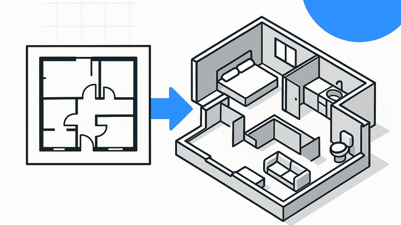
Turning a black and white floor plan to 3D is one of the fastest ways to visualize layout, verify circulation, and communicate design intent. Whether you’re planning a remodel, staging a listing, or evaluating unit mix in a building, a faithful 3D model transforms flat lines into spatial insight. The challenge? Achieving accuracy and visual clarity without getting lost in noisy scans, skewed images, or missing dimensions.
This guide covers a practical, end-to-end approach: cleaning your plan for reliable detection, calibrating true scale, choosing the right conversion method (manual, CAD, or AI-driven), applying materials and lighting that read realistically, and running a rigorous QA pass. By the end, you’ll be equipped to convert almost any black-and-white floor plan to 3D with confidence.
Start with a Clean Plan
High-quality input minimizes rework and prevents geometry errors during conversion.
- Resolution: Aim for 300–600 DPI if scanning. For photos, fill the frame, use even lighting, and avoid glare.
- De-skew and crop: Correct perspective so walls are parallel, then crop away margins, punch holes, binding, or title blocks not needed for modeling.
- Contrast and thresholding: Increase contrast so walls and symbols read as crisp black lines on a white background. Remove smudges and specks that can confuse auto-detection.
- Line weight consistency: If possible, normalize line thickness. Extremely thin or broken lines may become gaps; extremely thick lines can misrepresent wall thickness.
- File formats: PNG or high-quality JPG works well. PDF is fine if it’s a clean vector or a high-resolution image. Avoid overly compressed files.
Scale Is King: Calibrate Early
Everything in 3D depends on correct scale. Before tracing or running any AI conversion, set scale once and lock it.
- Best-case: Use a known dimension line (e.g., 12' 0" or 3650 mm) to calibrate. Pick the longest reliable dimension for reduced relative error.
- Fallback: Use a doorway or a bath fixture with known standards (e.g., a typical 80" door). Document any assumptions.
- Check aspect ratio: If a plan was photographed at an angle, height and width can stretch differently. Fix perspective before scaling.
Scale before style. Establish true scale, then work on walls, doors, windows, and finishes.
Conversion Methods Compared
There are several ways to convert a black and white floor plan to 3D. Choose based on time, accuracy needs, and collaboration.
| Method | How It Works | Pros | Cons | Best For |
|---|---|---|---|---|
| Manual Modeling (DCC/BIM) | Import plan as background; trace walls, place doors/windows, extrude. | High control; precise; works with complex geometry. | Time-intensive; steep learning curve. | Architectural detail, custom elements. |
| CAD Trace + 3D | Trace in CAD to clean vector, then generate 3D or export to 3D app. | Clean, scalable geometry; good for documentation. | Extra steps between CAD and 3D. | Renovations, measured drawings. |
| AI-Based App | Upload plan; AI detects walls, openings, rooms; outputs 3D. | Fast; user-friendly; good baseline accuracy. | Quality depends on input; may need edits. | Home planning, quick visualizations. |
| Photogrammetry | Use photos of existing space to build 3D; align to plan. | Great for as-built context; materials captured. | Needs site access; not plan-based alone. | As-built validation, renovations. |
Step-by-Step Workflow
- Prepare and import: Bring your cleaned plan into your tool of choice. Set units (ft/in or mm) and calibrate scale to a known dimension.
- Walls and thickness: Trace or auto-detect walls. Confirm wall thickness against notes (e.g., 4.5" interior, 6" exterior). Align corners and check for closures.
- Openings: Place doors and windows. For missing sizes, use sensible defaults and mark them for later verification.
- Levels and heights: Set floor-to-ceiling height, sill heights for windows, and stair riser/tread counts if shown or inferred.
- Rooms and labels: Assign room types for easier material presets and area checks. If your plan includes room names and sizes, capture them.
- Fixtures and built-ins: Add kitchens, baths, closets, and MEP symbols where provided. If the plan is schematic, add placeholders.
- Furnish strategically: Focus on anchor pieces first (sofa, bed, table) to establish circulation. Use standard sizes to avoid misjudging fit.
- Materials and lighting: Apply floor finishes and wall paints; set daylight through windows and a simple interior lighting rig to read space forms.
- Top-down validation: Generate a top orthographic view and overlay it on the original plan at matching scale for quick detection of drift.
- QA pass: Measure critical spans again, inspect door swings and clearances, and export a draft render for review feedback.
Materials and Lighting That Read
Even a modest material and light setup can clarify massing and scale without turning the project into a rendering marathon.
- Neutral base: Use a mid-gray wall, light wood or neutral tile floor, and white ceilings. This emphasizes geometry over decoration.
- PBR textures: Prefer physically based materials with realistic roughness and normal maps. Avoid tiled repetitions by rotating or varying UV scale.
- Daylight + practicals: Combine a sky/solar light with a few area lights or emissives for fixtures. Keep color temperature consistent (e.g., 4000K neutral).
- Clarity over drama: High-contrast shadows can hide edges. Use soft, even light to make dimensions legible.
Furniture for Realistic Space Planning
Use standards so your 3D reads like reality, not a collage of oversized pieces.
- Sofa depth: 36–40" (915–1015 mm)
- Dining clearance: 36" (915 mm) around table minimum
- Bed clearances: 24–30" (610–760 mm) on sides, 36" (915 mm) at foot
- Circulation corridors: 36–42" (915–1065 mm)
- Toilet front clearance: 21–24" (535–610 mm) minimum
QA Checks and Tolerances
Treat QA as part of modeling, not an afterthought.
- Tolerance targets: Residential schematic studies often accept +/- 2% error on spans, or +/- 1" (25 mm) on small runs. For documentation, tighten considerably.
- Diagonal checks: Compare diagonal vs. orthogonal measures to catch skew. If diagonals are off, revisit de-skewing and scale.
- Door/window verification: Confirm swing directions and clearances. Ensure doors don’t collide with each other or with fixtures.
- Overlay test: Export a top-down 3D view and overlay it on your plan in a graphics editor at the same scale. Misalignments pop out visually.
- Print at scale: A simple 1:50 or 1/4"=1'-0" print reveals drift and mismatched openings quickly.
Common Pitfalls and How to Fix Them
- Low-resolution scans: Re-scan at higher DPI or request the original PDF. If impossible, sharpen carefully and increase contrast.
- Perspective skew from photos: Use perspective correction tools so horizontal and vertical lines are truly orthogonal.
- Inconsistent line weights: Apply a threshold to unify. Consider re-drawing the outline quickly in CAD for a cleaner base.
- Missing dimensions: Annotate assumptions and prefer long-span calibrations for lower relative error.
- Ambiguous symbols: Verify legends. If a symbol is unclear, leave a placeholder and note it for stakeholder review.
- Curved or angled walls: Model with arcs and reference points; avoid approximating curves with many tiny segments that bloat geometry.
Data Hygiene, Privacy, and Collaboration
Plans often include addresses, owner names, or unit IDs. Keep deliverables clean and versioned.
- Redact PII: Blur or crop any personally identifiable information before sharing screenshots or exports.
- Version naming: Use consistent file names that encode date and scale. Keep source, working, and export folders separate.
- Share compactly: For feedback, export a lightweight 3D walkthrough or a few key renders instead of heavy project files.
Sample naming scheme for rooms and files:
{
  "project": "Johnson_House_A",
  "version": "v03",
  "scale": "1_4in_1ft",
  "rooms": [
    { "name": "Living_Room", "area_sqft": 182, "ceiling_ft": 9 },
    { "name": "Kitchen", "area_sqft": 120, "ceiling_ft": 9 },
    { "name": "Primary_Bedroom", "area_sqft": 150, "ceiling_ft": 9 }
  ]
}
Mini Case Example: 900 sq ft Apartment
Here’s a realistic path for converting a small, black-and-white floor plan to 3D.
- Input: Single-page PNG at 4000 px width, clear linework, a 12' dimension noted at the living room span.
- Calibrate: Set the 12' dimension. Verify the bedroom dimension reads within +/- 1" of the printed note.
- Walls and openings: Auto-detect walls; correct three window widths that were misread due to heavy line weight. Place doors with 80" height default.
- Heights: No ceiling height provided; assume 9'. Note the assumption in the model metadata.
- Fixtures: Drop in a 30" range, 36" counter depth for the fridge alcove, and a 60" tub. Mark the kitchen island as “to confirm.”
- Furnish: Queen bed, 84" sofa, 36" dining clearance, and a 60" round dining table to test circulation. One chair removed to improve flow.
- Materials and lighting: Light oak floor, neutral paint, cool-neutral 4000K area lights. Add window light to reveal depth.
- QA: Overlay top-down 3D with the plan; find a 0.75" drift on one wall from photo skew—corrected with re-scaling. Print at 1/4"=1'-0" for final check.
- Output: Export a 2000 px hero render, a top-down axon view, and a quick video walkthrough for stakeholder review.
FAQ
Can any black-and-white floor plan to 3D conversion achieve perfect accuracy?
If the plan includes full dimensions and is properly de-skewed, you can achieve highly accurate results. Without dimensions, expect reasonable approximations anchored to known elements. Document assumptions and validate with overlays.
Do I need elevations to create a convincing 3D?
Not strictly, but elevations improve window heights, trim, and cabinetry accuracy. In their absence, use typical standards and communicate where placeholders are used.
What if the plan uses unusual line conventions?
Consult the legend if available. Where symbols differ from your library, create or adapt custom components, and keep a symbol key for consistency.
How do I handle split-level or multi-story plans?
Model each level with its own elevation datum. Align stair openings carefully and check total rise/run against riser counts to prevent vertical mismatches.
Pro Tips for Faster, Better Results
- Work from big to small: Walls and openings first; fixtures next; furniture and styling last.
- Lock reference layers: Prevent accidental nudges of the imported plan by locking it before tracing.
- Use section cuts: A couple of clean sections help spot ceiling conflicts or stair headroom issues.
- Template smartly: Create room presets (e.g., Bath 5x8, Galley Kitchen) to speed up repetitive layouts.
- Iterate with stakeholders: Share early, low-fidelity views to get layout approval before polishing materials.
Key Takeaways
- Start with a clean, high-contrast plan and fix perspective before modeling.
- Calibrate scale early and verify with multiple dimensions.
- Choose the right conversion method for your project scope and timeframe.
- Use realistic materials and lighting that communicate space clearly.
- Run a rigorous QA: overlays, measurements, and prints at scale.
With these practices, you’ll turn a black and white floor plan to 3d efficiently and accurately—reducing guesswork and producing visuals that genuinely support decision-making.
For a quick, mobile-first approach to converting a black-and-white floor plan to 3D, an iOS app like Floor Plan to 3D can upload your plan photo, use AI to preserve proportions, and export high-resolution renders for presentations—handy when you need trustworthy visuals without a full desktop pipeline.
