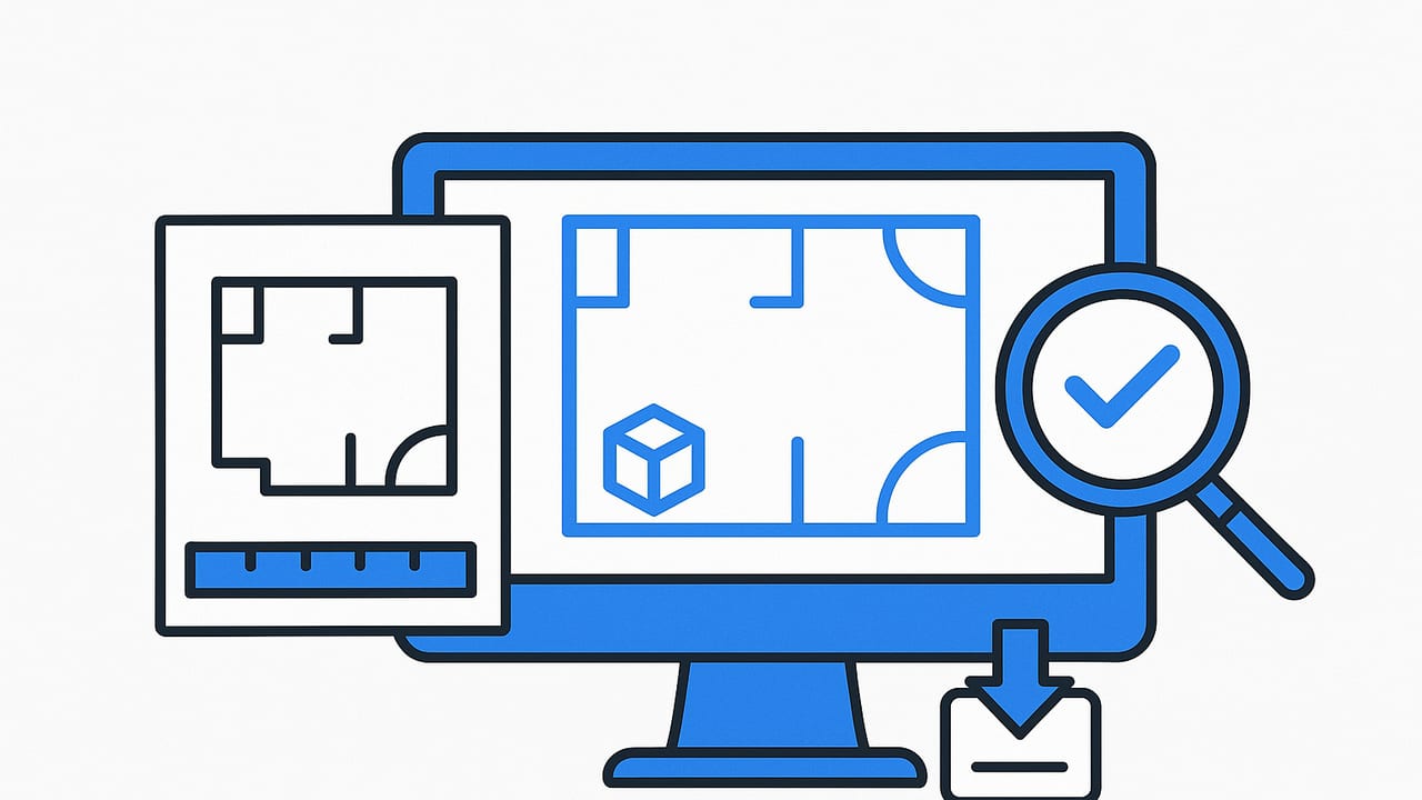
Turning a paper floor plan or PDF into a dependable digital model is now practical for homeowners, designers, and real estate pros. The goal is not just a pretty visualization, but an accurate room planner from scanned layout data that preserves scale, geometry, and intent. This guide walks you through a complete, tested workflow to capture, calibrate, build, verify, and export room and home layouts that hold up to measurement.
What qualifies as a scanned layout
A scanned layout can be any non-native plan image you import into a planner, including:
- A phone photo of a printed plan
- A flatbed scan of a paper drawing
- A rasterized page exported from a PDF
- Black and white linework with or without a scale bar
Accuracy hinges on input quality. Common issues include lens distortion from phone cameras, perspective skew if the photo was not shot straight on, low resolution from heavy compression, and faint lines that confuse edge detection. The more you reduce those issues up front, the less you will fight them later while building an accurate room planner from scanned layout files.
End to end workflow at a glance
- Capture it right
- Use flat, even lighting; avoid glare on glossy paper.
- If photographing, shoot perpendicular to the page with the camera centered and parallel to the plan. Fill the frame to maximize resolution.
- Enable grid lines on your camera to level the shot. If available, use a document scanning mode that corrects perspective.
- Prep the file
- Crop tightly to the plan edges. Remove borders and notes that are not needed.
- Increase contrast so lines are dark and backgrounds are light. Desaturate to grayscale if the tool performs better with black and white.
- Target at least 300 dpi equivalent. For photos, aim for 2500 to 4000 pixels on the long edge.
- Calibrate scale
- Use a known dimension on the plan, a scale bar, or a room width annotated on the drawing.
- Calibrate once per drawing and apply across the model. Recheck after any rotation or crop.
- Trace or auto-extract walls
- Prefer centerline tracing if the tool supports wall thickness. Otherwise, trace to one wall face and set a global wall thickness.
- Snap corners and align to orthogonal axes when appropriate. Use constraints to keep lines parallel or perpendicular.
- Add openings and structure
- Place doors and windows using the scanned layout as a visual guide. Enter exact sizes from annotations when available.
- Include columns, stairs, and HVAC chases so furniture planning reflects real constraints.
- Set heights and levels
- Assign floor to ceiling heights, sill heights, and head heights. These are essential for clash-free 3D visualization.
- Furniture and fixtures
- Insert items at true manufacturer sizes. Use parametric objects to maintain scale when swapping styles.
- Respect clearance standards for circulation, doors, and windows.
- Materials and lighting
- Apply finishes for realistic renders, but do not allow cosmetic choices to mask measurement errors.
- Use neutral lighting first to ensure geometry reads correctly.
- Quality assurance
- Check critical spans against plan dimensions. Validate room areas and corridor widths.
- Perform a door swing and window alignment pass.
- Export and document
- Export 2D, 3D, and bill of materials as needed. Embed scale metadata when possible.
How to calibrate scale from a scanned plan
Scale calibration transforms pixels into real units. If you want a truly accurate room planner from scanned layout imagery, this step is non negotiable.
Method A: Known dimension
- Identify a labeled dimension, such as a 12 ft 0 in wall.
- Measure that same wall in pixels using your planner or an image tool.
- Compute the pixel to unit ratio and apply it globally.
Method B: Scale bar or drawing scale
- Use the scale bar as your reference length, or input the drawing scale such as 1:50.
- Some tools let you draw a calibration line over the bar and input the real length.
Practical code example
The logic is simple: one known real world length paired with pixel length yields a scale factor. Here is a compact example you can adapt if your workflow allows scripting.
# Calibrate pixels to meters from a known segment

def calibrate_scale(px_length, real_length_m):
    assert px_length > 0 and real_length_m > 0
    return real_length_m / px_length  # meters per pixel

# Convert any pixel distance to meters

def px_to_m(px, m_per_px):
    return px * m_per_px

# Example: the plan says a wall is 4.00 m. You measured 812 pixels.

m_per_px = calibrate_scale(812.0, 4.0)
wall_m = px_to_m(812.0, m_per_px)  # should be 4.0

# If your tool stores coordinates in pixels, multiply all x,y distances by m_per_px.
If your image has perspective skew, calibrate along the same direction as your measurement, or correct the image first. Consistency beats perfect math in a distorted source image.
Common error sources and how to mitigate them
| Source | Symptom | Mitigation | Typical impact |
|---|---|---|---|
| Perspective skew | Walls that should be parallel converge | Use document scan mode, or deskew in an editor before import | 1 to 5 percent |
| Low resolution | Blurry lines, uncertain corners | Rescan at higher dpi or retake photo closer to the plan | Up to 3 percent |
| Wrong scale factor | All dimensions off by a constant | Calibrate using two or more known spans and average | 1 to 10 percent |
| Wall thickness assumption | Room areas slightly wrong | Set correct wall thickness per plan legends | 0.5 to 2 percent |
| Lack of snapping | Tiny gaps, misaligned corners | Enable snapping and constraints during tracing | Variable |
Rule of thumb: if you control capture and calibration, your error should sit comfortably under 1 percent for most rooms. Over 2 percent suggests either skew or calibration drift.
Quality assurance for an accurate room planner from scanned layout
QA is where accuracy becomes trustworthy. Use a short, repeatable checklist.
Dimensional spot checks
- Pick three critical spans per floor such as the longest wall, the kitchen run, and the bedroom width. Verify they match the plan within your tolerance.
- Check at least one diagonal across a room to validate that right angles are truly right.
Area validation
- Compute room areas and compare to labeled areas if the plan includes them.
- Sum areas per zone or apartment and compare to the plan totals where available. A difference over 2 percent warrants rechecking scale.
Openings and circulation
- Swing doors in the model. Confirm they clear adjacent objects and do not intersect walls.
- Confirm corridor widths meet code or design intent, typically 900 to 1000 mm minimum in residential settings.
Stacked elements
- Verify vertically aligned items such as windows on multiple floors share consistent heights.
- Check stair rises and runs for realistic geometry.
Export sanity test
- Export a 2D plan with a ruler overlay or dimension lines. Print at scale and measure with a physical ruler to cross check one or two spans.
Furniture planning that stays true to size
Once your envelope is accurate, furniture planning becomes reliable. Use real dimensions from manufacturers to avoid scale drift.
- Beds: queen 60 x 80 in or 1524 x 2032 mm; king 76 x 80 in or 1930 x 2032 mm.
- Sofas: common 84 in or 2134 mm long; allow at least 900 mm circulation in front.
- Dining: a rectangular table 1800 x 900 mm needs 900 mm clear on pull sides for chairs.
- Kitchen: 600 mm base cabinet depth; 1000 to 1200 mm aisle for two person work zones.
- Doors: leave 150 to 300 mm beyond latch side for comfortable swing clearance.
Maintain object libraries with locked dimensions and tags for clearance requirements. When experimenting with different styles, swapping a sofa should not alter length unless you intentionally pick a new size.
Interoperability and export options
Teams often need both visualization and documentation. Plan your outputs ahead of time.
- 2D images: PNG or SVG for annotated plans. Include a scale bar and at least two dimension strings on key spans.
- 3D assets: GLTF or OBJ for downstream visualization. Keep scene units in meters or feet and include a note on intended units.
- Print: set a target scale such as 1:50. For raster exports, compute pixel size to achieve 300 dpi at your print dimensions.
Quick print size math
# Print a 10 m wall at 1:50 on paper 300 dpi
# Wall on paper = 10 m / 50 = 0.2 m = 200 mm = 7.874 in
pixels = 7.874 * 300  # about 2362 px for that span
Include a scale bar on every print. If someone photocopies the plan, the bar still communicates true size even if absolute scale changes.
When to remeasure on site
A scanned layout is only as good as its source. Revisit the site when:
- The plan is older than the last known remodel.
- Field conditions reveal new chases, soffits, or wall furring not shown.
- You are planning tight fits such as built ins, appliance alcoves, or ADA clearances.
- Ceiling heights vary by room or slope, affecting cabinet or door selections.
Use a laser measurer to confirm at least one long span per room and update your scale if needed. Many tools let you lock a few as built dimensions while keeping the rest proportional.
Privacy, permissions, and provenance
Obtain permission to scan or photograph plans that are not yours. Remove personal data like names and unit numbers if the model will be shared. Keep an audit trail of the source file, capture method, and calibration references. This provenance helps explain small differences and avoids disputes later.
Checklist: a dependable workflow in 10 steps
- Capture straight, well lit, high resolution imagery.
- Crop and enhance contrast to clarify edges.
- Calibrate using at least one known dimension; verify with a second.
- Trace walls with snapping and consistent wall thickness.
- Place doors, windows, and structural elements.
- Assign heights and levels.
- Insert furniture and fixtures with true sizes.
- Run the QA checks for spans, areas, and circulation.
- Export with scale metadata and a visible scale bar.
- Document sources and calibration logic for future edits.
Choosing tools for an accurate room planner from scanned layout
Look for capabilities that minimize manual error:
- Reliable import of photos, scans, and PDFs
- One click scale calibration from a known length or scale bar
- Snapping, constraints, and wall thickness handling
- Door and window libraries with parametric sizing
- Room area auto calculation and dimensioning
- 3D preview that respects wall heights and openings
- Export options for images and 3D with preserved units
If you prefer a mobile first workflow that converts black and white plans to true to scale 3D quickly, consider Floor Plan to 3D, which can import a scanned layout, preserve proportions with AI, and export high resolution 3D images for presentations.
Final thoughts
An accurate room planner from scanned layout data is the bridge between a static drawing and confident design decisions. Capture cleanly, calibrate once, trace with constraints, and verify with a lightweight QA routine. With a disciplined approach and the right tooling, your 2D scan becomes a reliable 3D basis for layouts, furniture placement, and project communication.
