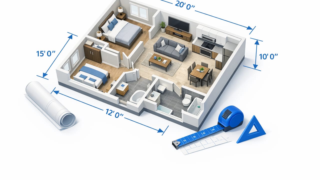
A 3d floor plan with dimensions is one of the fastest ways to move from “I think this will fit” to “I know it will fit.” It combines the clarity of a measured 2D plan (room sizes, wall lengths, openings) with a 3D view that helps people understand volume, circulation, and sightlines. The challenge is accuracy: if dimensions drift during conversion, the 3D render becomes persuasive—but unreliable.
This guide explains a practical, accuracy-first workflow to create a 3D floor plan that preserves the original plan’s proportions, labels, and dimensions, plus a checklist for validating results before you share them with a contractor, client, or design team.
What “3D floor plan with dimensions” really means
The phrase is often used loosely. For decision-making, it should mean:
- 3D geometry you can visually interpret (walls, doors, windows, sometimes ceiling height and stairs).
- Dimension fidelity: wall lengths and room sizes match the source plan after a known scale is applied.
- Readable annotations: key dimensions, room labels, and sometimes area (sq ft / m²).
- Exportable output: images/PDFs for reviews and proposals, and optionally a model format if needed.
In other words: it’s not just a pretty render. It’s a measured visual that survives scrutiny.
When you should insist on dimensions in the 3D output
Dimensions matter most when a decision depends on clearance, fit, or code constraints. Typical scenarios include:
- Kitchen planning (aisle widths, appliance clearances, island spacing).
- Bathroom renovations (fixture clearances, door swings, shower sizes).
- Basement finishing (egress windows, stair headroom, mechanical zones).
- Furniture planning and staging (sofas, beds, dining tables, circulation paths).
- Investor or client approvals where stakeholders need both “feel” and “facts.”
Rule of thumb: If a mistake would trigger rework, delays, or wasted purchases, make dimensions part of the 3D deliverable—not a separate afterthought.
Inputs: start with the cleanest plan you can
Conversion accuracy depends heavily on what you feed into the process. The best inputs are:
- Original PDF from an architect, builder, or listing packet.
- High-resolution scan (300 DPI or higher) of a paper plan.
- Phone photo only if it’s shot straight-on with even lighting (avoid skew and shadows).
Minimum info to confirm before you convert
- At least one known reference measurement (e.g., a labeled wall length).
- Clear indication of wall thickness if available (or a consistent assumption).
- Door/window markers or symbols that aren’t ambiguous.
Accuracy-first workflow: from plan to 3D with dimensions
Below is a workflow that works whether you’re using CAD, a 3D app, or an AI-assisted converter. The steps are tool-agnostic so you can adapt them to your setup.
1) Confirm scale and choose a calibration measurement
Even when a plan “looks” to scale, your conversion tool still needs a reference. Pick a dimension that is:
- Clearly labeled (e.g., “12'-6\"”).
- Long enough to reduce rounding error (a long exterior wall is ideal).
- Unlikely to be distorted (avoid small interior segments if the scan is skewed).
2) Straighten and clean the plan image (if needed)
If you’re starting with a scan or photo, small distortions can cascade into measurable drift. Before conversion:
- Deskew the image so walls are horizontal/vertical where intended.
- Increase contrast so wall lines are crisp.
- Crop tightly to the plan to reduce background noise.
3) Trace walls, then lock wall thickness assumptions
Many dimension errors happen when wall thickness is inconsistent. Decide early whether your dimensions represent:
- Exterior face to exterior face (often used for building footprint).
- Interior face to interior face (often used for room size and furniture planning).
- Centerline dimensions (common in some drafting conventions).
Be consistent. If your source plan uses interior dimensions but your 3D conversion measures exterior faces, you’ll appear “off” even if geometry is correct.
4) Place openings and validate swings/clearances
Doors and windows influence layout decisions more than most people expect. After placing openings:
- Check door swing direction and collision zones.
- Confirm window widths match the plan (or at least their proportions).
- Verify that opening placement aligns with dimension strings (if provided).
5) Add room labels and areas (optional but helpful)
Room labels and areas don’t just improve readability—they help catch mistakes. If a “Bedroom” label ends up in a hallway, something shifted. If the living room area is dramatically different from expectations, a wall likely moved.
6) Generate the 3D view and set heights deliberately
Most floor plan conversions default to a standard wall height. If you’re using the 3D plan for renovation previews, set:
- Ceiling height (8 ft vs 9 ft changes the feel and window proportions).
- Door height (standard vs taller doors).
- Stair geometry if included (rise/run affects headroom perception).
7) Overlay dimension strings and run a measurement audit
Before you export, validate a handful of measurements across different parts of the plan:
- One long exterior wall length
- Two interior wall segments
- At least one room width and one room depth
- One doorway opening width
If more than one measurement is off, the issue is usually scale calibration or image distortion—not a single misplaced wall.
Common dimension problems (and how to fix them)
| Problem | What it looks like | Most likely cause | Fix |
|---|---|---|---|
| Measurements are consistently off by the same % | Every wall is slightly too long/short | Wrong scale reference | Recalibrate using a longer labeled dimension |
| One side matches, the other drifts | Rooms on the right are “stretched” | Skewed photo/scan perspective | Deskew/warp-correct the image before conversion |
| Room sizes feel wrong even though some walls match | Rooms shrink/grow subtly | Wall thickness interpretation mismatch | Switch between interior/exterior face dimensioning consistently |
| Doors don’t fit cleanly in walls | Openings overlap corners | Tracing errors or unclear symbols | Manually correct openings; confirm swing and jamb location |
A quick scale check (with a simple calculation)
If you need to sanity-check scaling, you can compare a measured pixel distance between two points on the plan image to the real-world distance. Here’s a tiny example in Python-like pseudocode:
# Given: two points in image coordinates (pixels)
# and a known real-world distance for that segment
import math

p1 = (120, 340)
p2 = (980, 340)
known_distance_ft = 24.0

pixel_distance = math.dist(p1, p2)
ft_per_pixel = known_distance_ft / pixel_distance

# Now convert any pixel length to feet
some_wall_pixels = 310
some_wall_ft = some_wall_pixels * ft_per_pixel
print(some_wall_ft)
This won’t replace a full dimension audit, but it helps you detect a bad calibration early—before you build details on top of the wrong scale.
How to present a 3D floor plan with dimensions for stakeholders
Different viewers need different levels of detail. A practical set of exports includes:
- Top-down 3D floor plan with key dimensions (overall footprint + major rooms).
- Perspective 3D views for “feel” (2–4 angles).
- Annotated 2D snapshot if contractors prefer traditional reading.
Dimension density: don’t overload
Too many dimension strings can make the plan harder to use. Prioritize:
- Overall exterior dimensions
- Main room widths/depths
- Critical clearances (kitchen aisles, bath spacing)
- Door widths where accessibility matters
Practical example: remodeling a small kitchen without guesswork
Imagine you’re deciding whether to add an island. A measured 3D plan lets you test options quickly:
- Confirm the kitchen interior width (dimensioned).
- Place base cabinets and appliances at standard depths.
- Insert an island candidate (e.g., 24–36 in deep).
- Verify clearances: common targets are roughly 36–42 in for walkways (varies by layout and local norms).
- Export two versions (with and without island) and compare circulation in 3D.
Even if you later refine details with a professional, this workflow prevents early decisions based on distorted visuals.
Quality checklist before you export
- Scale: At least three dimensions match the source plan within an acceptable tolerance.
- Wall logic: Wall thickness is consistent and aligned with how the plan is dimensioned.
- Openings: Doors/windows are placed where the plan indicates and don’t collide with corners.
- Labels: Rooms are correctly named and placed.
- Readability: Dimension strings are legible at the export resolution.
- Versioning: Your exported file name includes revision info (e.g., “v2-after-wall-move”).
Choosing a tool: what to look for (beyond pretty renders)
If you’re selecting software or an app specifically for creating a 3d floor plan with dimensions, evaluate:
- Dimension preservation (does it keep proportions and allow measurement checks?).
- Plan recognition for black-and-white blueprints (walls, text labels, symbols).
- Easy correction tools (move a wall, fix an opening, adjust scale without restarting).
- Export quality (high-resolution images/PDFs suitable for proposals).
- Speed to iterate (renovation decisions require multiple alternatives).
Final thoughts
A 3D plan becomes truly useful when it’s both visual and measurable. By calibrating scale, staying consistent about wall thickness, and auditing a handful of critical dimensions, you can produce a 3D floor plan that supports confident renovation previews and clearer collaboration.
If you prefer an iOS workflow that converts floor plans into clean 3D visuals while keeping key layout details readable, Floor Plan to 3D & Home Redesign is one option to explore.
