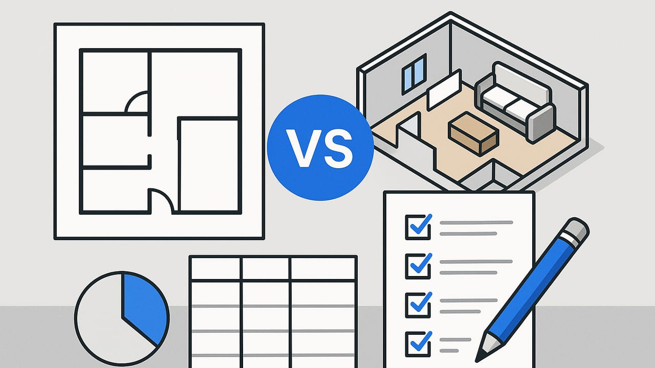
Floor plans are the language of spatial decision-making. Whether you’re renovating a kitchen, listing a property, or coordinating trades on a job site, choosing between 2D and 3D affects how clearly everyone understands the design, how quickly you iterate, and how reliably the final build meets expectations.
“Plans are decisions made visible.” The clearer the plan, the fewer surprises on site.
This guide compares 2D and 3D floor plans feature by feature, shows where each excels, and outlines a simple workflow to combine them effectively. If you’ve been trying to compare 2D vs 3D floor plan options for your project, use this as your decision framework.
The Quick Answer
- 2D floor plans are best for drafting, measuring, permitting, and rapid iteration. They speak the technical language of scale, dimension strings, and annotations.
- 3D floor plans are best for comprehension, stakeholder alignment, material decisions, furniture fit, and marketing. They communicate volume, daylight, and flow in seconds.
- Use both when accuracy and buy-in are critical: draft in 2D, validate and present in 3D, and loop back for revisions.
Feature-by-Feature Comparison
| Criteria | 2D Floor Plans | 3D Floor Plans | Impact |
|---|---|---|---|
| Comprehension for non-experts | Moderate; requires reading symbols | High; intuitive visuals | Fewer miscommunications with clients and buyers |
| Scale accuracy & dimensions | Excellent with proper drafting | Excellent if model honors inputs | Both can be precise; QA is essential |
| Spatial relationships & clearances | Abstract; needs interpretation | Concrete; see volume and fit | Reduces collision/clearance errors |
| Circulation & ergonomics | Good for path diagrams | Great for sightlines and reach | Improves layout comfort |
| Lighting & shadows | Not represented | Visualized with materials/time of day | Better finish and lighting choices |
| Material & finish decisions | Notes/specs only | Preview in context | Aligns expectations, reduces returns |
| Furniture & appliance fit | Measured, but abstract | True-to-scale 3D context | Avoids door swings and pinch points |
| Structural coordination | Strong for dimensions/sections | Strong when modeled; clash checks | Fewer site conflicts |
| Accessibility & code checks | Dimensions verify clearances | Visual verification of reach/maneuver | Better compliance confidence |
| Marketing & sales appeal | Baseline listing asset | High-impact visuals | Faster decisions from buyers/tenants |
| Revision speed | Fast for line edits | Fast with parametric tools | Depends on tool and workflow |
| Cost to produce | Generally lower | Varies; higher if photoreal | Pick by purpose and ROI |
| Printability | Excellent at multiple scales | Good as stills; interactive needs screens | Choose outputs by audience |
| Stakeholder alignment | Good with experienced teams | Excellent for mixed audiences | Fewer meetings and rework |
When to Use 2D, When to Use 3D
Use 2D Floor Plans When:
- You’re capturing measurements on site, tracing existing conditions, or doing quick test fits.
- Creating permit sets with dimension strings, notes, and details.
- Coordinating structural grids and MEP routes using annotations and layers.
- Producing printable plans for bidding and takeoffs.
Use 3D Floor Plans When:
- Presenting concepts to clients or stakeholders unfamiliar with drawings.
- Validating furniture layout, appliance clearances, and door swings.
- Reviewing lighting, materials, and sightlines between spaces.
- Marketing listings or proposals with high-impact visuals.
Use Both When:
- You need both technical accuracy and universal clarity.
- Stakeholders are remote and decisions need to be rapid.
- Projects carry risk from misinterpretation (tight spaces, custom millwork).
A Simple 2D-to-3D Workflow
- Capture or import your 2D base. Scan a printed plan or export a clean PDF/DWG. Confirm scale bars and key dimensions.
- Normalize layers and units. Ensure walls, doors, windows, and fixtures sit on consistent layers; standardize to metric or imperial.
- Model walls and openings. Extrude walls from 2D lines, add door/window elements with correct heights and swings. Validate bounding box dimensions against the plan.
- Place fixed elements. Stairs, plumbing fixtures, appliances. Check rough-ins and code clearances (e.g., 30 in cooktop clearance).
- Add movable furniture. Use true-to-scale blocks or parametric objects. Verify circulation paths (e.g., 36 in around dining table).
- Apply materials and lighting. Assign finishes; set daytime and interior lighting to evaluate contrast, glare, and mood.
- QA loop. Cross-check 3D dimensions against the 2D plan. Run a quick checklist (below), then export stills or an interactive model.
3D QA Checklist
- Critical room dimensions match 2D (±1% or specified tolerance).
- Door swings clear adjacent elements; no handle collisions.
- Stair geometry meets rise/run and headroom requirements.
- Appliances have service clearances and ventilation.
- Primary pathways meet target width and accessibility needs.
- Window heights align with exterior elevations and furniture placement.
Example: A Kitchen Remodel in 2D vs 3D
Scenario: A 12 ft by 14 ft kitchen, island planned at 36 in by 84 in, refrigerator by the entry, and a 30 in range on the exterior wall.
2D-only outcome: The plan shows compliant dimensions, but the refrigerator door swing and the island overhang aren’t intuitive to the homeowner. They approve the layout.
3D validation: In a 3D view, the family sees that opening the refrigerator door pinches the walkway to 30 in when the dishwasher is open. They also notice upper cabinets conflict with a window header. The island is reduced to 72 in, the refrigerator shifts 9 in, and the upper cabinets are redesigned. The final built space matches expectations, and installation day has fewer surprises.
Lesson: 2D confirmed compliance; 3D prevented ergonomic and sequencing issues that compliance alone didn’t reveal.
Common Pitfalls and How to Avoid Them
2D Pitfalls
- Under-annotating: Missing door swings or section markers cause field confusion. Include symbols and legend.
- Scale drift: Scans or screenshots without scale bars lead to wrong measurements. Always validate two known dimensions.
- Layer noise: Overlapping legacy layers obscure what’s current. Clean layers before sharing.
3D Pitfalls
- Pretty but wrong: Photoreal images can mask dimension errors. Cross-check critical metrics directly in the model.
- Performance bloat: High-poly furniture or PBR textures slow devices. Use optimized assets and level-of-detail settings.
- Lighting misreads: Overexposed renders hide detail. Calibrate exposure; test day and night scenes.
Cost and Time: A Practical View
Costs vary by tool and labor market, but the pattern is consistent: 2D is typically cheaper per iteration, while 3D saves time by preventing misunderstandings and rework. Consider where your project’s risk lies—if stakeholder buy-in or spatial fit is critical, 3D quickly pays for itself.
| Phase | 2D Effort | 3D Effort | Risk of Rework |
|---|---|---|---|
| Initial concept | Low | Low–Medium | Medium (misinterpretation) |
| Design development | Medium | Medium | Low with 3D validation |
| Client presentation | Medium | Low–Medium | Lowest with visuals |
| Construction coordination | Medium | Medium | Low (fewer clashes) |
Deliverables and File Formats
- 2D: DWG/DXF for CAD teams, PDF for universal sharing, and scaled prints (A3–ARCH D). Include a legend and north arrow.
- 3D: Stills (PNG/JPEG), interactive (GLB/USDZ) for AR/VR or web viewers, and exchange formats (OBJ/FBX/IFC) if coordinating across platforms.
- Metadata: Keep a simple title block and revision index across both so teams match the latest version.
Decision Matrix: Pick the Right Tool for the Moment
| Scenario | Recommended | Notes |
|---|---|---|
| Permit submission | 2D primary | Include dimensions, symbols, code notes |
| Client concept review | 3D primary + 2D backup | Use 3D for buy-in, 2D for specifics |
| Tight urban remodel | Both | 2D for exact fits, 3D to avoid ergonomic issues |
| Sales listing | 3D primary | Renderings accelerate decisions |
| Trade coordination | 2D + targeted 3D | Use 3D for clashes and sequences |
Presenting to Stakeholders
- Start with 3D to set context fast—one hero view per room or a short walkthrough.
- Follow with 2D to discuss dimensions, outlets, and exact placements.
- End with decisions summarized in a punch list tied to drawing sheets or view names.
Checklist: Compare and Combine 2D and 3D
- Identify your audience (permit reviewer, client, contractor, buyer).
- List the top three decisions needed (layout, finishes, budget fit).
- Choose the driver: 2D (accuracy/permits) or 3D (clarity/marketing).
- Build the minimum viable set: one 2D plan, two 3D views per key room.
- Run the 3D QA checklist against critical dimensions.
- Export deliverables with consistent naming and revision tags.
- Record approvals tied to specific sheets or views.
Key Takeaways
- 2D is the backbone of measurement and compliance; 3D is the accelerator of understanding and alignment.
- Most projects benefit from both: draft in 2D, validate and sell in 3D.
- Quality control beats aesthetics alone—trust the dimensions, then build the visuals.
If you’re looking to turn a black-and-white plan into a true-to-scale 3D view on your phone, the iOS app Floor Plan to 3D can convert photos or scans into detailed 3D models you can export for proposals and presentations.
