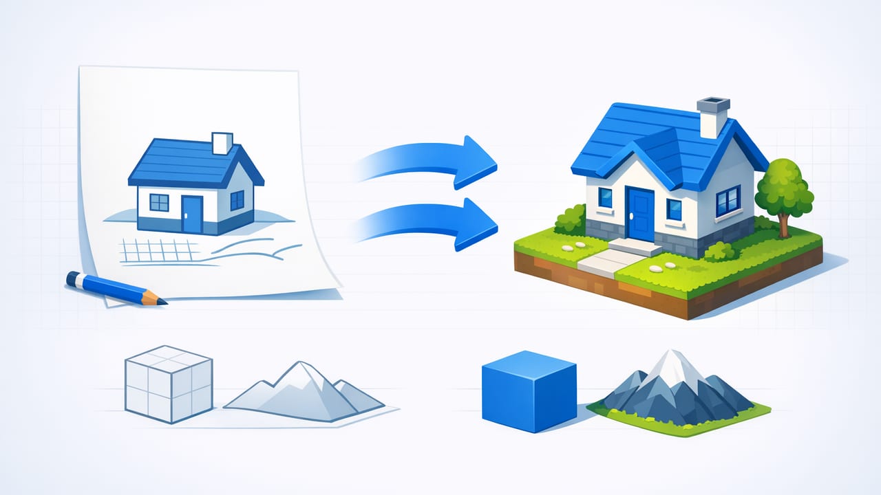
2D to 3D conversion turns a flat floor plan into a spatial model you can walk through, measure, and present. Done well, it preserves the plan’s proportions and clearances while adding depth (wall height), openings (doors/windows), and context (materials, furniture, lighting). Done poorly, it creates a “pretty” image that quietly breaks reality—misplaced doors, stretched rooms, and furniture that doesn’t fit.
This guide explains a practical, accuracy-first workflow for converting black-and-white 2D floor plans into reliable 3D visuals—whether you’re a homeowner planning a remodel, a designer iterating layouts, or a real estate pro preparing presentations.
Why 2D to 3D conversion changes decision-making
A 2D plan is great for dimensions and code-style clarity, but it’s harder to feel scale. Converting to 3D helps you:
- Validate flow (hall widths, door swings, pinch points)
- Catch conflicts (windows blocked by cabinets, furniture blocking circulation)
- Compare options faster (kitchen islands, room swaps, wall removals)
- Communicate clearly to stakeholders who don’t read plans daily
“The real value of 3D isn’t decoration—it’s eliminating expensive surprises by seeing space the way people actually experience it.”
Start with the right input: plan quality matters
Most conversion errors come from the input. Before you model anything, check the plan source and legibility:
Common 2D sources (best to worst for automation)
- Vector PDF / CAD (DWG/DXF): clean lines, consistent scale, easiest to interpret
- High-resolution scanned plan: workable if straight and well-contrasted
- Phone photo of a printed plan: usable, but distortion and shadows must be corrected
Preflight checklist for your floor plan image
- Straighten so walls are horizontal/vertical (reduce perspective skew)
- Increase contrast so wall lines read clearly
- Remove clutter (coffee stains, handwritten notes over walls)
- Ensure a known dimension exists (one labeled wall length is enough to scale)
- Confirm the plan is complete (no cropped edges; include scale bar if available)
AI-assisted vs. manual modeling: what each is best at
Today’s AI-based architectural visualization can speed up layout recognition dramatically, especially for black-and-white plans. But you still need human checks around scale, openings, and assumptions (like wall height). Here’s a practical comparison:
| Approach | Strengths | Watch-outs | Best for |
|---|---|---|---|
| Manual CAD-to-3D | High control; precise constraints | Time-intensive; steep learning curve | Professionals needing full editability |
| BIM workflow | Data-rich; documentation-friendly | Heavy setup; overkill for quick concepts | Construction-grade modeling |
| AI + mobile 3D rendering | Fast 2D recognition; quick iterations | Needs verification (scale, symbols, edge cases) | Room planning, remodel options, presentations |
The step-by-step workflow for accurate 2D to 3D conversion
Use this workflow regardless of tool. The order matters because early mistakes compound later.
Step 1: Establish scale (the non-negotiable step)
A 3D model is only as accurate as its scale. Choose one reliable reference dimension from the plan (e.g., “12'-0\"” living room width) and calibrate everything to that.
If you’re working from an image, the basic math is:
// pixel_to_meter_scale
// known_length_m: a labeled wall length converted to meters
// measured_pixels: pixel distance between the same two points on the image
scale_m_per_px = known_length_m / measured_pixels

// any measured pixel length can be converted:
length_m = pixel_length * scale_m_per_px
Tip: Use the longest labeled dimension you can find. Longer references reduce error from imprecise clicks.
Step 2: Trace or confirm the wall layout
Walls define the model’s “truth.” When converting, treat walls as centerlines or faces consistently—don’t mix methods between rooms.
- Confirm wall thickness (interior vs exterior often differ)
- Check for double lines that indicate thicker construction
- Resolve ambiguous areas (stairs, shafts, fireplaces) early
Step 3: Place doors and windows (and verify swings)
Openings are where most “looks right” models fail. In 2D, symbols can be stylized; in 3D, they must be functional.
- Door width: verify standard sizes or read labels if provided
- Door swing direction: confirm it doesn’t collide with fixtures or furniture
- Window placement: align to walls and check sill height assumptions
Quick validation: In a hallway, open every door virtually. If two doors clash, something is wrong (either plan interpretation or placement).
Step 4: Add heights (the missing dimension)
Most 2D plans don’t encode full vertical information. You’ll often need to assume or collect:
- Ceiling height (common defaults exist, but confirm when possible)
- Door height and transoms (if any)
- Window head/sill heights
- Stair rise/run if stairs are in scope
Best practice: Document assumptions in a simple note (for yourself or your client). If a decision is based on an assumption, label it.
Step 5: Define zones and usage (room planning comes next)
Before placing furniture, confirm room boundaries and intended use. A “den” vs “bedroom” changes furniture defaults and clearance expectations.
- Label rooms (kitchen, dining, bedroom, bath)
- Mark fixed elements (plumbing walls, columns, built-ins)
- Note circulation paths (entries, hallway routes, primary walk lines)
Step 6: Furnish with real clearances (not just aesthetics)
Furniture in 3D is valuable when it’s dimensionally honest. Use typical clearance rules:
- Walkways: keep primary paths comfortable and consistent
- Dining: allow chair pull-back clearance
- Kitchens: check appliance door swings and work zones
- Bedrooms: ensure access on at least one side of beds (preferably both)
If your 3D view reveals that a “standard” sofa blocks a doorway, that’s a success—not a failure. You found an issue while it’s cheap to change.
Step 7: Apply materials and lighting for readable renders
Architectural visualization doesn’t need to be hyper-realistic to be useful. Aim for clarity:
- Material discipline: limit to a few finishes per space (floor, wall, cabinetry)
- Neutral lighting: avoid overly dramatic shadows that hide geometry
- Camera height: choose human-eye level for walkthrough views
Step 8: Export views that answer specific questions
Different outputs serve different stakeholders. A good export set usually includes:
- Top-down furnished plan view: validates layout efficiency
- Two to four interior perspectives: communicates feel and scale
- One “problem corner” view: highlights tight areas (entries, bathrooms)
- High-resolution images: suitable for proposals or presentations
Accuracy pitfalls (and how to avoid them)
These issues show up repeatedly in 2D to 3D conversion projects:
1) Perspective distortion from phone photos
If you photographed a plan at an angle, walls won’t be orthogonal in the image. Correct perspective or re-capture the photo square-on.
2) Misreading line weights
Thicker lines might indicate exterior walls, but not always. When in doubt, cross-check with dimension strings and door/window placement.
3) Ignoring interior wall thickness
Even small thickness errors compound across rooms and can shift openings enough to break furniture fit.
4) Assuming missing dimensions
If the plan lacks a key measurement (like an overall width), use one known dimension to scale and then verify at least two other labeled distances to confirm consistency.
A simple QA checklist before you share the 3D
- Scale check: verify 2–3 labeled dimensions match the 3D model
- Door/window check: openings align, swings make sense, sizes are plausible
- Clearance check: no furniture blocks doors, key paths are walkable
- Height check: ceiling/door/window heights are consistent and documented
- Export check: images are high-resolution and named clearly by room/view
When to iterate vs. when to “lock” the model
A useful rhythm is:
- Iteration phase: fast 3D drafts to test layout options (move walls, swap room functions)
- Validation phase: verify measurements, resolve openings, confirm assumptions
- Presentation phase: materials, lighting, and clean exports for stakeholders
Locking too early leads to rework; presenting too early leads to feedback on finishes before the layout is correct.
Choosing tools for your workflow
The best tool is the one that matches your required accuracy and turnaround time. If your goal is quick room planning and clear communication, an AI-assisted mobile workflow can be ideal. If you need construction documents, you’ll likely want a CAD/BIM pipeline.
For those who want a streamlined iOS approach to turning black-and-white plans into dimension-aware 3D visuals, Floor Plan to 3D is one option to explore at the end of your tool comparison—especially for fast concepting and export-ready renders.
